What's new
British Ordnance Collectors Network

This is a sample guest message. Register a free account today to become a member! Once signed in, you'll be able to participate on this site by adding your own topics and posts, as well as connect with other members through your own private inbox!

4.7" Coast Gun case markings

Falcon

Well-Known Member
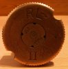
Here is a diagram I have drawn of the headstamp of a 4.7" Coast Gun case I bought at Detling last weekend.

Does anyone know what the three symbol markings are? They are the two broken concentric circles above "RL", the flower-like symbol and the square with the bits inside.

Also, does "F 19" indicate it was loaded again with a full charge in 1919 or is it just a lot number?

Finally, what does the large "T" under 1903 mean?

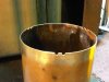
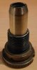
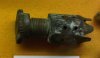
This case had been filed down by around 3mm to remove the notches as obviously some previous owner thought they shouldn't be there. However I have turned the very end of the neck off so that it looks right. I intend to file the notches back in when I get time. As it was otherwise such a nice case I thought it was worth retoring. It is about 6mm short now but I can live with that.

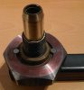
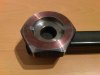
The primer is also present, which is usually missing on these as the case won't stand up with it in place. The outer ring of the primer is marked: "RL II E.O.A.C. V /|\ 12/01". the inner is also marked "R/|\L IV". What does "E.O.A.C." stand for? Was the primer reworked or reloaded by Elswick?

I have made a tool to try and loosen the primer but at the moment it will not move. I am planning to try soaking it in diesel next.

Thanks for any info.
 

Attachments

  • 4.7_hs.GIF
    4.7_hs.GIF
    5.6 KB · Views: 116
I re-cut the notches on the top of the case this week. They look like they are not at an equal angle around the top of the case but it is the angle of the photo. I think they came out alright.

The case is now standing in the workshop with diesel in to hopefully loosen the primer.
 

Attachments

  • notches.jpg
    notches.jpg
    86.3 KB · Views: 43
I managed to free the primer today after filling the case with diesel and standing for 2 weeks. It made all the difference, the primer came out easily with my tool I made for it. Before the soaking in diesel, when the same tool was used it would not budge.
 
Last edited:
Can you post a photo of the primer? I'm noticing that these external primers seem to differ due to case length and caliber. Also, could you show the tool you made? I'm currently soaking a couple of 12Pdr casings, a short one with the short primer that was shown a few days ago in another post, and a taller case that has a longer primer. I want to try to remove them as you have done.

Thanks,

John
 
Here are the photos of the primer and the tool.

The vent tube appears to have been fired by an electrical contact that made the chequerboard pattern on the primer rather than a percussion firing pin.
 

Attachments

  • primer_in_tool.jpg
    primer_in_tool.jpg
    67.5 KB · Views: 43
  • primer_rear.jpg
    primer_rear.jpg
    77.5 KB · Views: 54
  • primer_side.jpg
    primer_side.jpg
    77.1 KB · Views: 42
  • tool_closeup.jpg
    tool_closeup.jpg
    48.4 KB · Views: 46
  • tool_full.jpg
    tool_full.jpg
    70.2 KB · Views: 43
Falcon

Very nice tool building skills you have! Did you make the head from a hardened tool steel and use hard pins? I have two 12Pdr cases, a short one and a long one with the primers currently stuck in place, and I need to make a tool to get them out. My 4.7 inch case has no primer, so I was going to make one, but I needed to see what your copy looked like.

The reason I asked, was because I have one removeable primer in a tall 12Pdr case that has a long perforated vent tube on it, which is completely different from any photos or drawings that I have seen posted here.

Thanks so much for posting the photos!

Does anyone have any idea how many calibers and case types used these external quick/change primers?

John
 
Last edited:
I made the tool from ordinary mild steel. I used hexagonal bar as it already had flat edges which made marking out the holes for the pins easier. I drilled and tapped the holes first and then bored out the large hole that the primer slots into. The pins are ordinary half thread M6 allen screws which I screwed tightly into place and then hacksawed off and turned the ends flat.
 
The reason I asked, was because I have one removeable primer in a tall 12Pdr case that has a long perforated vent tube on it, which is completely different from any photos or drawings that I have seen posted here.

I came across this diagram of a 12 Pounder blank earlier. It has a long perforated vent tube on the primer. Perhaps your 12 Pounder case was a blank?

http://web.ukonline.co.uk/stephen.johnson/arms/blank12.jpg
 
The blank idea sounds as good as any. The tube on mine doesn't look like the one in your photo though. Mine is shorter with larger holes through the tube, and the tube is just a straight pipe shape, not closed on the end like in your blank drawing.

Thanks for posting the drawing!
 
Here is a picture of another primer, found this in a museum of ship wrecks. Sorry for the bad quality, taken through glass on a phone. Well at least it looks like it fits the bill ?
Best regards Weasel.
 

Attachments

  • IMG00474-20100925-1253.jpg
    IMG00474-20100925-1253.jpg
    57.8 KB · Views: 23
That is one strange primer Weasel! Thanks for showing it. This strange primer thing could have a thread all it's own.
 
Obviously the magazine on that one would have to have been screwed on once the primer was screwed into the case. It is strange that it appears to be fired yet is screwed together and is out of the case. Why would someone on board a ship have removed it then fitted the two parts back together?
 
Top