What's new
British Ordnance Collectors Network

This is a sample guest message. Register a free account today to become a member! Once signed in, you'll be able to participate on this site by adding your own topics and posts, as well as connect with other members through your own private inbox!

Casting terminology

Snufkin

Well-Known Member
Premium Member
I’d appreciate if anyone can help with identifying the origin of the term centre cast, used by some collectors to describe the lathe finished versions of some of the early No.5 Mills grenade bodies.

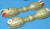
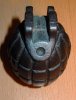
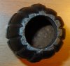
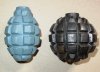
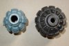
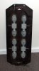
Mills grenades are found mostly cast as two vertical halves (akin to an Easter egg) around a vertical central axis, as this minimises subsequent machining. However, an early alternative in the No.5 family was as a bottom half and a top half - in order to allow the patterns to be removed from the mounds only the vertical grooves of the segmentation could be cast in. The horizontal segmentation grooves had be turned on a lathe. A good example is shown in the recent thread by Infanteer, “Early No5 Mills bomb”.

I have not encountered the term to describe any particular orientation of mould sections in die casting and sand casting generally. Equally I have never seen the term referred to in any period manufacturing or inspection documentation of the Mills grenade. Centre cast strikes me as a being a modern misnomer, in that there is no more of a centre around which the casting is made with bottom and top halves, as compared to vertical sections.

Anyone got any ideas as to why “centre cast”? Anyone skilled in the art of casting who can say as to what the two types of casting should be correctly labelled? Thanks.


Tom.
 
Last edited:
Tom,

You may have heard me use the term 'transverse casting'. Its origin is lost I regret to say but I thought I picked it up from something official. Presumably the early No 5 Specs add nothing useful to the subject?
 
Tom,

You may have heard me use the term 'transverse casting'. Its origin is lost I regret to say but I thought I picked it up from something official. Presumably the early No 5 Specs add nothing useful to the subject?


Norman,

Thanks. I don't recollect "transverse" in any of the documentation (and I will revisit it), but it is a far more accurately descriptive term than centre cast. If nothing else turns up, I for one would happily adopt it.


Tom.
 
Cast in 2 pieces to remove the pattern? Dosen't this require the halves to be welded? Wouldn't they just be cast with a core in the center of the sand mold to make the hollow for the filler and internal parts?
 
Cast in 2 pieces to remove the pattern? Dosen't this require the halves to be welded? Wouldn't they just be cast with a core in the center of the sand mold to make the hollow for the filler and internal parts?


The patterns are used to make the imprints into the two sand boxes – the cope (top box) and the drag (bottom box). The cope and drag are accurately aligned together with a casting sand core held within the cavity, and the molten metal poured. A complete casting, for example grenade body, results (no welding necessary…). Breaking away the sand core leaves the body space of the grenade ready for drilling and threading.

A transverse casting of a Mills body cannot be made with horizontal grooves in situ, without the sand mould crumbling as the pattern is removed.


Tom.
 
Last edited:
The raw casting is hollow, due to the sand core that was placed in the mould. The photos show:

1. Patterns for making the body imprints in the drag and cope - image courtesy of Dano1917 in a previous Mills grenade thread (thanks Dano).

2. Cores being made from casting sand. These create the cavity in the raw casting.

3,4. The final result - here a raw No.5 casting awaiting drilling and countersinking of the striker and filler holes, milling of pivot slots, threading of mouth to take centrepiece and base plug, etc.


Tom.
 

Attachments

  • Patterns for No.36.jpg
    Patterns for No.36.jpg
    97.2 KB · Views: 57
  • Mould cores for No.36.jpg
    Mould cores for No.36.jpg
    11.8 KB · Views: 59
  • Raw casting No.5_1.jpg
    Raw casting No.5_1.jpg
    90.4 KB · Views: 49
  • Raw casting No.5_2.jpg
    Raw casting No.5_2.jpg
    60.4 KB · Views: 46
Sand Cast;

If you compare your grenade to a artillery shell it could have been cas in the same way, either vertical or horizontal.
The sand core which forms the explosive cavity is supported by a metal pin or plug and the outer boxes will form the outside of the shell. Perhaps the sprew and vent holes point are at a different positon is up to the moulder. After the casting has cooled the boxes are opened and the shell knocked from its sand mould and the inner sand core is removed through the fuze or filler hole and the holes threaded for fuze and or bottom plug in the case of the grenade. In any case the sand box is re-filled with itts pattern and the process repeated. Usually there will be multiple shells cast at one time. The sand mould is lost each time.
hope this helps.
John aka Bart
 
Last edited by a moderator:
Thanks John. Exactly as you say, for shells, grenades, bombs, mortar bombs, etc.

Attached is a close up of sand moulds for Mills No.36 being filled.


Tom.
 

Attachments

  • Grenade sand moulds.jpg
    Grenade sand moulds.jpg
    25.5 KB · Views: 58
Casting;

Yes, that is a neat image. Too bad there is not one showing the release from the moulds
There should be not need for machineing. Casting sand of today can be packed so tight and hard it is alomst like smooth clay. It can be sifted and used over again many times.
There is no reason why both horizontal and vertical fragmentation grooves can't be cast. I have never held a Mills grenadebut I bet if you take a close look at the grooves they are cast at a slight angle to aid release of the pattern. Both the pattern and the final sand mould are dusted with a mould release agent to aid removal of the pattern, the sand is not going to break up. I have watched patterns being made in the ship's pattern shop and then a visit to the foundry to watch the metal castings being made. It is facinating to watch and dangerous for the foundrymen.
Regards,
john aka Bart
P.S. My drawing shows a metal mould vice a sand box.
 
Believe it or not I used to work in a small foundry, we did investment castings through the wax loss process. So sand casting is new to me.
 
casting

I found this photo someplace......... after the casting process of course, but interesting nonetheless.
 

Attachments

  • CAV Mills production.jpg
    CAV Mills production.jpg
    100.7 KB · Views: 43
I first heard the term from Mike Saffery. If anyone knows when it was first used it might be Mike.

John
 
Thanks to all for comments.

Having looked through a fair few documents, I cant find the term centre cast. If anyone does find a period document with it, please say. However, the terms transverse and longitudinal are much used in engineering, and accurately describe the two types of Mills grenade casting.

As for examples other than Mills, the French F1 grenade design used from WWI onwards is a longitudinal casting. The 1913 model German Kugel grenade is transverse, and the grooves immediately above and below the centre line segmentation band would have required machining.

The F1 illustrates well the slight tapering of the pattern necessary to aid release of the pattern as the sand mould is made. This tapering effect is also seen on the longitudinal Mills castings.


Tom.
 

Attachments

  • DSC02584.jpg
    DSC02584.jpg
    94.4 KB · Views: 19
  • DSC02587.jpg
    DSC02587.jpg
    79.2 KB · Views: 14
Here is a photo of a casting board for MK II bodies that I was able to take one day while viewing a friends' collection.
 

Attachments

  • casting board.jpg
    casting board.jpg
    85 KB · Views: 36
Top