What's new
British Ordnance Collectors Network

This is a sample guest message. Register a free account today to become a member! Once signed in, you'll be able to participate on this site by adding your own topics and posts, as well as connect with other members through your own private inbox!

Early type No. 80 fuze cover?

Darkman

Well-Known Member
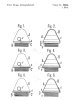
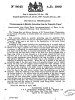
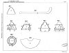
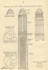
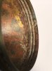
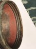
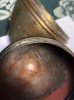
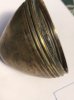
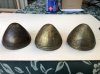
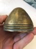
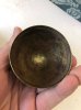
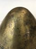
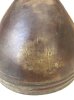
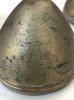
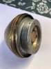
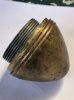
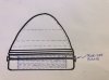
These photos show the early type fuze covers for the No. 80 Mks I, II, III & IIIA aluminium fuzes. I’m not sure how they were attached to the fuze or enclosed the fuze to keep it sealed. Maybe the cover was soldered to a cup washer that went over the fuze thread, or perhaps the fuze was fully enclosed with a shallow cup tin (as per my drawing)? I just don’t know as I’ve never seen a complete one. I believe the early covers had a tear-off band like the later types as there is remnant solder on the screwed in ring. It wasn’t until the No. 80 Mk IV fuze that had a screwed on brass ring as the bottom skirt that the covers were then soldered to the fuze skirt itself including subsequent fuze marks. Does anyone know exactly how these early fuze covers were secured, or have one they could show, or a drawing? The manuals have very scant information and just mention a threaded ring, but the threaded ring appears to have been soldered to something.
Thanks for any info, Graeme
 

Attachments

  • ED8370CE-1AE0-4002-8F9A-379FD0DE3F8A.jpeg
    ED8370CE-1AE0-4002-8F9A-379FD0DE3F8A.jpeg
    125 KB · Views: 37
  • 89341842-648A-4E04-AD1E-0826BE6E744A.jpeg
    89341842-648A-4E04-AD1E-0826BE6E744A.jpeg
    96.7 KB · Views: 38
  • 5989F0C2-6C17-4C9A-9A37-176CB7EE469A.jpeg
    5989F0C2-6C17-4C9A-9A37-176CB7EE469A.jpeg
    100.3 KB · Views: 27
  • D46476BB-64D1-4E6C-A58C-5573A5C65AB5.jpeg
    D46476BB-64D1-4E6C-A58C-5573A5C65AB5.jpeg
    110.1 KB · Views: 24
  • 43602DA0-C990-4D13-B7B8-9828D1967883.jpeg
    43602DA0-C990-4D13-B7B8-9828D1967883.jpeg
    103.3 KB · Views: 23
  • 87471DBB-C67A-4EB6-A9F1-C1A2BCE0D3DB.jpeg
    87471DBB-C67A-4EB6-A9F1-C1A2BCE0D3DB.jpeg
    158.9 KB · Views: 25
  • F74EB34C-C4B0-459D-9056-B0BDD2D616E9.jpeg
    F74EB34C-C4B0-459D-9056-B0BDD2D616E9.jpeg
    106.4 KB · Views: 28
  • BE1F152F-0B38-4B11-819A-9057580941DB.jpeg
    BE1F152F-0B38-4B11-819A-9057580941DB.jpeg
    108.1 KB · Views: 31
  • AF8A2E2D-18FE-4B7D-9361-11CB0908B62C.jpeg
    AF8A2E2D-18FE-4B7D-9361-11CB0908B62C.jpeg
    114.4 KB · Views: 28
  • 74202082-CE7B-42F4-92C6-5F11C801E4D0.jpeg
    74202082-CE7B-42F4-92C6-5F11C801E4D0.jpeg
    92.6 KB · Views: 32
I think these old caps had no tear off band like the soldered more modern types but were screwed to their bottom part. They seem to have an Edison-like (lightbulb) sheet metal thread.

The later soldered protective caps are Krupp patented caps which were used by many other countries too. In the UK to my understanding Vickers patented it in the Name of Krupp. With modern words one could say "VSM held the rights for the UK market"
 

Attachments

  • FRIEDRICH KRUPP41-3.jpg
    FRIEDRICH KRUPP41-3.jpg
    214.8 KB · Views: 35
  • GB190908645A_Original_document_20221019151913_0000.jpg
    GB190908645A_Original_document_20221019151913_0000.jpg
    288 KB · Views: 28
  • GB190908645A_Original_document_20221019151913_0004.jpg
    GB190908645A_Original_document_20221019151913_0004.jpg
    135.3 KB · Views: 33
Last edited:
The NOTES ON THE AMMUNITION FOR Q.F. 13-PR, Q.F 18-PR, Q.F. 4.5-INCH HOWITZER, 1915 is showing at least a picture of your cap on the right side (I hope). So it's at least clear that these caps were mounted on the complete cartridge and that no single fuzes were packaged in them. The question how exactly they were mounted remains. I wonder if there was a threaded part clamped in the joint between fuze and the fuze socket which could be removed only by unscrewing the fuze (sounds not like a good idea)
 

Attachments

  • notes-on-ammunition-for-13pr-18pr-4pt5-inch-how-1915_0008.jpg
    notes-on-ammunition-for-13pr-18pr-4pt5-inch-how-1915_0008.jpg
    288.6 KB · Views: 28
Last edited:
Thanks Alpini for the extra information, but I’m more confused than ever now! Your first post indicates that the tear-off strip design in British service only originated in 1909 (but the brass skirt fuzes weren’t in service then?). And your second post shows the threaded type cap on a fuze fitted to a shell, so the fuze threads must be exposed. So the method of sealing is still a mystery.

With these additional photos I’m trying to show that a separate ring is screwed into the cap threads and the bottom of this separate ring has remnant solder on it. My original photos show that the bottom of this threaded ring sits below the skirt of the fuze and also that the cap diameter is larger than the fuze itself. So there has to be another piece involved. Still no idea how it sealed the fuze!
 

Attachments

  • B8C531A8-F25C-4E7C-994F-89CFCF6941E6.jpeg
    B8C531A8-F25C-4E7C-994F-89CFCF6941E6.jpeg
    147.3 KB · Views: 14
  • 3E542171-E2D5-428C-9175-0649585B9700.jpeg
    3E542171-E2D5-428C-9175-0649585B9700.jpeg
    118.3 KB · Views: 12
  • F1C4BDF5-E8C5-422F-A892-4A7E5B79D555.jpeg
    F1C4BDF5-E8C5-422F-A892-4A7E5B79D555.jpeg
    135.2 KB · Views: 18
  • E14FCDA6-D9E4-456F-8711-E1782BE041BF.jpeg
    E14FCDA6-D9E4-456F-8711-E1782BE041BF.jpeg
    100 KB · Views: 10
  • 8DC45F2F-AFC0-4E25-A06A-7F9DFF9B23D1.jpeg
    8DC45F2F-AFC0-4E25-A06A-7F9DFF9B23D1.jpeg
    96.7 KB · Views: 13
Last edited:
Thanks now I understand (the construction of the caps on) your photos. I thought this inner ring isn't screwed into the cap but soldered and that the cap was screwed into another part.

I think I have seen another patent (not sure if from Krupp) about a threaded cap but cannot find it in my documents. I already spent hours of searching (being sick at home makes it possible) but without success.

When I read the parts of the manual of your older thread:

http://www.bocn.co.uk/vbforum/threa...ish-1905-fuze-cap-cover?highlight=fuze+socket

...then my theory would be that the cap was split into two parts connected through the tread for manufacturing reasons only. This way they could first solder the threaded ring to the fuze socket (probably with a copper block with a wooden handle heated up over a flame in 1905). Then the socket could be screwed back to the shrapnell, the shrapnell filled, fuze screwed in and as a last step the cap screwed in with the typical british read/brown sealing putty. After the putty dried the cap could not longer be removed by screwing so an additional "tin band" was required. Just with the "tin band" I have a small translation problem - I guess a "tin band" in this case isn't a band made of tin but a piece of steel wire which was used to open a tin?

To solder the later ~1909 fuze caps probably powerful electrical soldering irons were available. Soldering a live fuzed shrapnel in a room with an open flame to heat up the soldering iron couldn't have been a good idea.
 
Last edited:
Between the cap base and the threaded ring is a red colored petmann cement which sometimes overflows inside. Yes there is tin solder on the outside of the ring under the cap which is broken after removal and I think this solder must have been attached to the brass socket of the eye of the shell.
All caps found are complete and not séparate with the ring.
Some makers: B&S, EOC, Co i, C.O.W Ltd 1905, KN in a drum
 
Thank you Alpini and Doctor.

I have come to the same conclusion that realistically, the only thing the cap could be attached to is the fuze socket by soldering. And given the relative position of the cap bottom ring (even allowing for a felt protector in the nose of the cap and a washer on the fuze), it would have been soldered to the bottom section of the socket adapter - not the stepped portion. Possibly there was no stepped section on these early sockets anyway, as there was no need for it. This is further borne out by the diameter of the cap being some 3-4mm larger than the fuze diameter which would contact lower down the socket.
In relation to the “tin” tear-off band, this is more likely to have been brass but tinned with solder. The construction/appearance and dimensions of the tin band and method of removal is still unknown.

Graeme
 
Top