Well…. As we are in lockdown again over here in Holland I have time on my side to make some interesting write ups.
Let me start to thank Joop Dijkman of the MTM-DAWN museum in Landhorst for the great cutaway model of the No.208MkIII mechanical time fuze for the cutaway of the QF 3,7 inch HE shell. Although it’s a post war fuze it has only minor differences with the wartime fuze, and a wartime No.208 fuze in cutaway condition is rare as hen’s teeth over here (even false teeth).
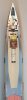
When I bought my 3,7 inch HE projectile it was fuzed with the No.199 igniferous nose fuze, but with both fuzes for the projectile described the story is more complete, especially as the No.208 was especially designed for the QF 3,7 inch anti-aircraft projectile.
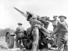
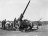
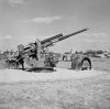
In the years just after the First World War, there was a growing awareness in England that a powerful heavy AA gun was needed for future threats from the air. The first plans were made in 1920, but it took until 1933 before the army command could give a clear description of what they wanted. In 1934 the Vickers company submitted the first designs for the Ordnance QF 3.7 inch AA gun to the army command, and in April 1936 the first working test model of the gun was delivered. In 1937 the Ordnance, QF (Quick Fire) 3.7 inch, Mark I, II and III” went into production, and the first guns were delivered in 1938. As the imminent threat of war became more apparent, production had to be rushed, and because gun mounts - both mobile and stationary - were complicated, gun mounts were produced by various manufacturers. The mobile gun carriages of the different manufacturers were therefore designated with the Mark I, IA, III and IIIA. Around the major cities and around important industrial and military installations guns were placed on fixed concrete installations (static mounts); the mounts of these guns were designated Mark II, IIA, B and C.
Here a link to a map showing the batteries of British heavy anti-aircraft artillery in fixed positions during World War II, to give you an idea of how many guns this was about. Note that each gun on the map is a battery of multiple guns;
http://www.anti-aircraft.co.uk/HAA_gun_sites_map.html
The QF 3.7 inch AA gun remained in service in UK until 1957 - albeit in a modified version, the Mark 6 - to be replaced by anti-aircraft missiles. Currently only Nepal still has 45 QF 3.7 inch AA guns in service, 84 years after the first guns rolled off the production line!
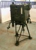
During production, the gun manufacturing process was simplified to increase production speed. Improvements were also made in the design, such as an automatic loading tray, an automatic fuze setter and a predictor (Photo 09). The latter is a device that uses input data such as the altitude, heading, angular velocity and speed of the enemy aircraft to calculate the time at which the time fuze is to be set and the direction and angle in which the barrel should be pointed for the projectile to be in the same spot as the enemy plane when the projectile detonates. With the static mounts the predictor is connected to the gun’s drive mechanism and points the gun in the calculated direction in a continuous process, as well as the fuze setter that adjusts the time to be set in a continuous process.
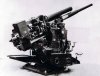
Altogether, the QF 3.7 inch gun was a very reliable and effective anti-aircraft gun that could easily compete with the German 8,8cm Flak 36/37 gun, only the latter had already earned a reputation as an anti-aircraft and anti-tank gun during the Spanish Civil War.
However, if the data from both guns is put side by side, the 3.7 inch gun is the better performer.
An armor-piercing shell was available for the 3.7 inch gun, but because of the gun mount design, the gun was not particularly suitable for horizontal fire. Also missing was a sight for horizontal (anti-tank) fire because the gun was designed purely as an anti-aircraft gun.
During the Battle of Britain in 1940 the gun was used with limited success as an anti-aircraft gun, the Igniferous time fuze No. 199 that was used at that time was not very accurate. From 1942 on however, the mechanical time fuze No.208 was used on the 3,7 inch HE shell, which was very accurate and used with great success at the end of the Second World War in the hunt for V1’s fired from the Netherlands, Belgium and France to London. Over 75% were shot down, however it should be noted that barrage balloons and fighters also had a considerable part in bringing down many doodlebugs.
Link:
https://www.youtube.com/watch?v=H95YuznbEYY
https://www.youtube.com/watch?v=WrYQEqNPskE
The Germans were very impressed with the QF 3.7 Inch anti-aircraft gun, and gratefully included the guns captured in Dunkirk in their own inventory as the '9.4cm Flak Vickers (e)'. When the captured ammunition ran out, 100.000 rounds were produced in February 1943. These shells have a double (FES) iron drivingband. Not only did the Germans manufacture bodies, they also ended up making fuzes. It appears all they did was cut a 2" thread on an AZ23.
Among collectors, these - now extremely rare- German manufactured projectiles are a wanted and sought-after item.
There are four types of shells available for the gun; the high explosive shell, the shrappnel shell, the armour piercing shell, and the practice shell. There is also a drill cartridge available as well as a clearing cartridge. In this posting only the HE shell is described.
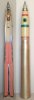
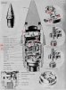
The high explosive projectile consists of a pressed and machined steel body at which a steel flange is placed in the base, secured by means of a roller seam. As the projectile body is pressed on a prress arbor , small - virtually invisible - cracks can occur that run through the entire bottom and end up in the explosives room, leading to a premature explosion of the projectile during travel through the barrel when high pressure hot gas leak into the explosive charge. To prevent this, a 10mm thick cut-out steel plate has been placed in the bottom to serve as a gas-tight seal.
The copper driving band is the same for all types of shells of the QF 3.7 inch anti-aircraft gun and is according to design D.D.(L)T. 6278A/1.
A cast explosive charge of TNT or a mixture of TNT and RDX, or RDX is cast in the shell body, in all cases 0.873 kg. The oldest shells had an Amatol explosive charge. In the top of the explosive charge a stepped cardboard tube is placed; in the lower stage a smoke box consisting of a bakelite bushing filled with red phosphorus has been placed to ensure a cloud of smoke remains at the detonation point in the air which allows for observation purposes. In the upper stage of the cardboard tube the CE pellet is placed, a thin cardboard canister with a better quality explosive (RDX), intended to ignite the explosive charge in the projectile simultaniously.
The space between the CE pellet and the bottom of the fuze is filled with impregnated cardboard rings, the so-called 'leatherboard rings'. The space in the projectile body above the cardboard canister and around the bottom of the fuze is filled with wax (white).
The shellcase is brass made and 675mm long. Percussion primer Mk.2 No.II. is screwed in the base of the shellcase. This percussion primer has a conical plug above the firing cap that ensures the flame of the firing cap is allowed to move upwards in the gunpowder magazine, but pushes the plug down and closes the firing cap for gas leakage backward when igniting the main charge in the shellcase.
The powder charge in the shellcase consists of 3.87 kg cordite sticks 522 mm long, with a diameter of 4.1 mm with a through hole of 1.2 mm. In the lower center of this cordite charge an elongated bag with coarse-grained gunpowder is placed that strengthens the flame of the percussion primer in the bottom of the shellcase.
On the top of the powder charge, a sheet of tin or lead foil 279 x 178 x 0.05 mm thick is wrapped around the powder charge, secured by means of webbing worsted. This is to keep the barrel clean; residual copper from the driving band -which mainly builds up in the corners of the grooves- mixes with the vaporized tin or lead to form a hard and brittle bronze alloy that is pushed out of the barrel by the next shell passing through the barrel. A simple trick to keep the barrel clean from unwanted copper contamination.
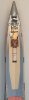
The projectile is ochre yellow in color, which indicates that it is a high-explosive shell. The green band indicates that the shell is filled with TNT, the red band at the top indicates that the shell is suitable for all climates. Had there been red crosses, this would have meant that the shell is limited suitable for hot or cold climates. The green dot indicates a smoke box is present in the projectile, a black stenciled A in the dot indicates the red phosphorus is placed in an Aluminum can, a black stenciled B indicates the red phosphorus is placed in a Bakelite can.
Igniferous time fuze No.199, description and function (fig 07):
The igniferous nose fuze No.199 was specially designed in 1925 for use on anti-aircraft shells and consists of a brass body (1) with a recess in the bottom in which the gunpowder magazine (2) is housed, closed with a brass cap (3). The top of the igniter body is tubular and the inertia-fired percussion cap (4) is fitted inside the tube. Two brass rings (5 and 6) with a igniferous composition are arranged around this tubular part, which form the time setting part of the fuze. The lower ring (6) is rotatable to set the time -maximum 30 seconds-, the upper ring (5) is not rotatable and is fixed by means of an axial pin. Both rings are locked up by an aluminum nose cap (7).
The fuze functions as follows; before firing, the time is set by rotating the lower ring (6) counterclockwise. The further it is trotated, the longer the burning time of the igniferous composition and –consequently- the delay. When fired, the percussion cap (4) moves backward due to inertia and hits the firing pin (9) riding the spring (8). The flame from the exploding percussion cap can move up and down and travel through one of two -or both- green channels (10 or 11) to the flame boosting gunpowder pellet (12). A hole (13) is drilled upwards in the lower ring so that the flame flashes from the upper to the lower ring when the burning igniferous composition has reached this hole. The fuse will then start to burn in the other direction until it reaches the hole to the magazine (14) in the flange of the fuze and the magazine (2) is ignited. The flame emerging from the bottom of the fuze ignites the Booster No.II Mk4, which in turn detonates the shell.
The reason for using two igniferous composition rings is twofold; the first reason is that one does not have to press the composition too hard so that the composition is not 'pressed to stone' and can therefore refuse to burn. The second reason is to divide the error that occurs with the direction of rotation of the shell and the burning direction of the fuze, during one half of the burning time the flame is pushed into the composition ring by the direction of rotation of the shell, the other half - if the flame has moved to the lower ring - the flame runs behind the composition while it burns. Since the length of the fuse to be burned in the upper and lower rings is the same, so the error in burning time is mediated.
A wooden ring has been fitted in the magazine (2) because less gunpowder is needed than can be filled and wood is cheaper than gunpowder.
The igniferous time fuze No.199 is used only on the 3.7 inch high-explosive shells in combination with the gaine No.11 Mk4 (images 07 and 08). This is because the igniferous fuze was actually intended for the 3.7 inch shrapnel anti-aircraft shell that can be ignited by means of a gunpowder flame. However, this flame is not strong enough to ignite the explosive charge in the high-explosive shell. That is why a separate booster (15) has been placed between the time fuze and the explosive charge; at the top of the booster is a flame-sensitive lead-azide detonator (16), at the bottom a C.E (tetryl) pellet (17), powerful enough to initiate the main charge in the high-explosive shell. Between the flame-sensitive detonator and the CE pellet is a centrifugal safety (18) which is out of line when in rest so the explosive chain is interrupted, but which is thrown out after firing the shell so that the explosion chain is aligned. On the left in image 08 the booster is at rest, on the right the booster is armed (after firing).
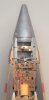
The Mechanical Time fuze No.208 Mk3, description and operation (Figure 06);
The first mechanical fuze for the 3.7" was the No.207, which like the 199 was an igniferous fuze.
The fuze No.208 is a detonating fuze and essentially just a fuze No.207 incorporating a gaine. However, this allowed the timer to be seated further into the fuze making it less susceptible to 'barrel slap' etc., resulting in a very reliable fuze.
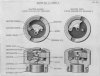
The No.208 fuze was put into use in 1942 and consists of a brass fuze body (19) in which the brass booster (20) is placed in the base, locked up by a threaded ring (21). The safety slide (22) is fitted on top of the booster, which interrupts the explosion chain in rest. In the safety slide there is an obliquely drilled channel that connects the percussion cap (23) under the firing pin (29) of the timer above it with the detonator (24) of the booster below. A spring wants to push the safety slide into the armed position, but the slider is fixed in the safe position by a spring-loaded axial pin (25, photo 05, only with the post war Mk.3 fuze). When the shot is fired, the pin will move backward by inertia, causing the slide to move to the left, closing the explosion chain.
Above the booster there is a partition (26) in the fuze housing. A spring-loaded clock (27) is placed above the partition. In fact clock is not the right word, the better word would be a kitchen timer; turning the aluminum nose cap (28) on top of the fuze sets the time and -like a kitchen timer- the time increases as the cap is turned further. At the end of the timer a hand is released that would activate the bell with a kitchen timer, with the fuze No.208 an arm connected to the firing pin is released that causes the firing pin to rotate so that a bulge on the side of the firing pin slides off a pin, allowing the spring loaded firing pin (29) to move downward into the firing cap (23). The arm is released when the sprong loaded hand (30, in photo 06) placed on top of the gear train fits the lock plate in the underside of the 'dome' (photo 06) and jumps upward. In rest, the hand (30) is fixed by the trigger (32,) which swings / rotates downward when the shot is fired and releases the spring-loaded hand to rotate until it fits into the lock plate (33) above it.
The ‘clock’ shows close resemblance to the clock found in the German Zt.Z.S30, which is used in many time fuzes up to this day.
The aluminum nose cap (28) contains a brass disc (34) with three small discs (35) at the bottom in a circular array, each secured by means of a screw to the brass disc (34) above it. These three small discs fall partly outside the disc above and fall into three semicircular recesses in the nose cap (28). The three discs are placed above three axial pins (36). After setting the clock and firing the shell, the disc with the three discs below moves backward due to the inertia and pushes the three pins down, locking the cover against further rotation, fixating the time setting of the clock.
The upper brass disc is fixed in the safe position by means of three radial brass pins (37) and will shear the three pins when the shell is fired as the assembly moves backwards due to inertia.
Since the time fuze No.208 Mk.III no longer has setting marks with seconds and fractions of seconds are marked on the outer edge of the fuze body for the purpose of manual setting of the fuze, I suspect that the fuze is meant for setting with the gun mounted and controlled fuze setter only, not for manual setting with a hand setting key.
Complete cartridge length : 1083mm.
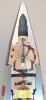
Projectile length (with fuze No.208) : 440mm.
Projectile weight : 12,6 kg.
Ceiling : 9760 mtr (32000 feet).
Countries that have used the QF 3,7 Anti aircraft gun:
Australia, Belgium, Canada, Cyprus, Germany (as spoils of war), India, Jugoslavia, Ireland, Israël, Malta, Nepal (45 still in service), New Zealand, Pakistan, Poland (as part of the British army), Portugal, Sri Lanka, South Africa.
Regards, DJH
Let me start to thank Joop Dijkman of the MTM-DAWN museum in Landhorst for the great cutaway model of the No.208MkIII mechanical time fuze for the cutaway of the QF 3,7 inch HE shell. Although it’s a post war fuze it has only minor differences with the wartime fuze, and a wartime No.208 fuze in cutaway condition is rare as hen’s teeth over here (even false teeth).
When I bought my 3,7 inch HE projectile it was fuzed with the No.199 igniferous nose fuze, but with both fuzes for the projectile described the story is more complete, especially as the No.208 was especially designed for the QF 3,7 inch anti-aircraft projectile.
In the years just after the First World War, there was a growing awareness in England that a powerful heavy AA gun was needed for future threats from the air. The first plans were made in 1920, but it took until 1933 before the army command could give a clear description of what they wanted. In 1934 the Vickers company submitted the first designs for the Ordnance QF 3.7 inch AA gun to the army command, and in April 1936 the first working test model of the gun was delivered. In 1937 the Ordnance, QF (Quick Fire) 3.7 inch, Mark I, II and III” went into production, and the first guns were delivered in 1938. As the imminent threat of war became more apparent, production had to be rushed, and because gun mounts - both mobile and stationary - were complicated, gun mounts were produced by various manufacturers. The mobile gun carriages of the different manufacturers were therefore designated with the Mark I, IA, III and IIIA. Around the major cities and around important industrial and military installations guns were placed on fixed concrete installations (static mounts); the mounts of these guns were designated Mark II, IIA, B and C.
Here a link to a map showing the batteries of British heavy anti-aircraft artillery in fixed positions during World War II, to give you an idea of how many guns this was about. Note that each gun on the map is a battery of multiple guns;
http://www.anti-aircraft.co.uk/HAA_gun_sites_map.html
The QF 3.7 inch AA gun remained in service in UK until 1957 - albeit in a modified version, the Mark 6 - to be replaced by anti-aircraft missiles. Currently only Nepal still has 45 QF 3.7 inch AA guns in service, 84 years after the first guns rolled off the production line!
During production, the gun manufacturing process was simplified to increase production speed. Improvements were also made in the design, such as an automatic loading tray, an automatic fuze setter and a predictor (Photo 09). The latter is a device that uses input data such as the altitude, heading, angular velocity and speed of the enemy aircraft to calculate the time at which the time fuze is to be set and the direction and angle in which the barrel should be pointed for the projectile to be in the same spot as the enemy plane when the projectile detonates. With the static mounts the predictor is connected to the gun’s drive mechanism and points the gun in the calculated direction in a continuous process, as well as the fuze setter that adjusts the time to be set in a continuous process.
Altogether, the QF 3.7 inch gun was a very reliable and effective anti-aircraft gun that could easily compete with the German 8,8cm Flak 36/37 gun, only the latter had already earned a reputation as an anti-aircraft and anti-tank gun during the Spanish Civil War.
However, if the data from both guns is put side by side, the 3.7 inch gun is the better performer.
An armor-piercing shell was available for the 3.7 inch gun, but because of the gun mount design, the gun was not particularly suitable for horizontal fire. Also missing was a sight for horizontal (anti-tank) fire because the gun was designed purely as an anti-aircraft gun.
During the Battle of Britain in 1940 the gun was used with limited success as an anti-aircraft gun, the Igniferous time fuze No. 199 that was used at that time was not very accurate. From 1942 on however, the mechanical time fuze No.208 was used on the 3,7 inch HE shell, which was very accurate and used with great success at the end of the Second World War in the hunt for V1’s fired from the Netherlands, Belgium and France to London. Over 75% were shot down, however it should be noted that barrage balloons and fighters also had a considerable part in bringing down many doodlebugs.
Link:
https://www.youtube.com/watch?v=H95YuznbEYY
https://www.youtube.com/watch?v=WrYQEqNPskE
The Germans were very impressed with the QF 3.7 Inch anti-aircraft gun, and gratefully included the guns captured in Dunkirk in their own inventory as the '9.4cm Flak Vickers (e)'. When the captured ammunition ran out, 100.000 rounds were produced in February 1943. These shells have a double (FES) iron drivingband. Not only did the Germans manufacture bodies, they also ended up making fuzes. It appears all they did was cut a 2" thread on an AZ23.
Among collectors, these - now extremely rare- German manufactured projectiles are a wanted and sought-after item.
There are four types of shells available for the gun; the high explosive shell, the shrappnel shell, the armour piercing shell, and the practice shell. There is also a drill cartridge available as well as a clearing cartridge. In this posting only the HE shell is described.
The high explosive projectile consists of a pressed and machined steel body at which a steel flange is placed in the base, secured by means of a roller seam. As the projectile body is pressed on a prress arbor , small - virtually invisible - cracks can occur that run through the entire bottom and end up in the explosives room, leading to a premature explosion of the projectile during travel through the barrel when high pressure hot gas leak into the explosive charge. To prevent this, a 10mm thick cut-out steel plate has been placed in the bottom to serve as a gas-tight seal.
The copper driving band is the same for all types of shells of the QF 3.7 inch anti-aircraft gun and is according to design D.D.(L)T. 6278A/1.
A cast explosive charge of TNT or a mixture of TNT and RDX, or RDX is cast in the shell body, in all cases 0.873 kg. The oldest shells had an Amatol explosive charge. In the top of the explosive charge a stepped cardboard tube is placed; in the lower stage a smoke box consisting of a bakelite bushing filled with red phosphorus has been placed to ensure a cloud of smoke remains at the detonation point in the air which allows for observation purposes. In the upper stage of the cardboard tube the CE pellet is placed, a thin cardboard canister with a better quality explosive (RDX), intended to ignite the explosive charge in the projectile simultaniously.
The space between the CE pellet and the bottom of the fuze is filled with impregnated cardboard rings, the so-called 'leatherboard rings'. The space in the projectile body above the cardboard canister and around the bottom of the fuze is filled with wax (white).
The shellcase is brass made and 675mm long. Percussion primer Mk.2 No.II. is screwed in the base of the shellcase. This percussion primer has a conical plug above the firing cap that ensures the flame of the firing cap is allowed to move upwards in the gunpowder magazine, but pushes the plug down and closes the firing cap for gas leakage backward when igniting the main charge in the shellcase.
The powder charge in the shellcase consists of 3.87 kg cordite sticks 522 mm long, with a diameter of 4.1 mm with a through hole of 1.2 mm. In the lower center of this cordite charge an elongated bag with coarse-grained gunpowder is placed that strengthens the flame of the percussion primer in the bottom of the shellcase.
On the top of the powder charge, a sheet of tin or lead foil 279 x 178 x 0.05 mm thick is wrapped around the powder charge, secured by means of webbing worsted. This is to keep the barrel clean; residual copper from the driving band -which mainly builds up in the corners of the grooves- mixes with the vaporized tin or lead to form a hard and brittle bronze alloy that is pushed out of the barrel by the next shell passing through the barrel. A simple trick to keep the barrel clean from unwanted copper contamination.
The projectile is ochre yellow in color, which indicates that it is a high-explosive shell. The green band indicates that the shell is filled with TNT, the red band at the top indicates that the shell is suitable for all climates. Had there been red crosses, this would have meant that the shell is limited suitable for hot or cold climates. The green dot indicates a smoke box is present in the projectile, a black stenciled A in the dot indicates the red phosphorus is placed in an Aluminum can, a black stenciled B indicates the red phosphorus is placed in a Bakelite can.
Igniferous time fuze No.199, description and function (fig 07):
The igniferous nose fuze No.199 was specially designed in 1925 for use on anti-aircraft shells and consists of a brass body (1) with a recess in the bottom in which the gunpowder magazine (2) is housed, closed with a brass cap (3). The top of the igniter body is tubular and the inertia-fired percussion cap (4) is fitted inside the tube. Two brass rings (5 and 6) with a igniferous composition are arranged around this tubular part, which form the time setting part of the fuze. The lower ring (6) is rotatable to set the time -maximum 30 seconds-, the upper ring (5) is not rotatable and is fixed by means of an axial pin. Both rings are locked up by an aluminum nose cap (7).
The fuze functions as follows; before firing, the time is set by rotating the lower ring (6) counterclockwise. The further it is trotated, the longer the burning time of the igniferous composition and –consequently- the delay. When fired, the percussion cap (4) moves backward due to inertia and hits the firing pin (9) riding the spring (8). The flame from the exploding percussion cap can move up and down and travel through one of two -or both- green channels (10 or 11) to the flame boosting gunpowder pellet (12). A hole (13) is drilled upwards in the lower ring so that the flame flashes from the upper to the lower ring when the burning igniferous composition has reached this hole. The fuse will then start to burn in the other direction until it reaches the hole to the magazine (14) in the flange of the fuze and the magazine (2) is ignited. The flame emerging from the bottom of the fuze ignites the Booster No.II Mk4, which in turn detonates the shell.
The reason for using two igniferous composition rings is twofold; the first reason is that one does not have to press the composition too hard so that the composition is not 'pressed to stone' and can therefore refuse to burn. The second reason is to divide the error that occurs with the direction of rotation of the shell and the burning direction of the fuze, during one half of the burning time the flame is pushed into the composition ring by the direction of rotation of the shell, the other half - if the flame has moved to the lower ring - the flame runs behind the composition while it burns. Since the length of the fuse to be burned in the upper and lower rings is the same, so the error in burning time is mediated.
A wooden ring has been fitted in the magazine (2) because less gunpowder is needed than can be filled and wood is cheaper than gunpowder.
The igniferous time fuze No.199 is used only on the 3.7 inch high-explosive shells in combination with the gaine No.11 Mk4 (images 07 and 08). This is because the igniferous fuze was actually intended for the 3.7 inch shrapnel anti-aircraft shell that can be ignited by means of a gunpowder flame. However, this flame is not strong enough to ignite the explosive charge in the high-explosive shell. That is why a separate booster (15) has been placed between the time fuze and the explosive charge; at the top of the booster is a flame-sensitive lead-azide detonator (16), at the bottom a C.E (tetryl) pellet (17), powerful enough to initiate the main charge in the high-explosive shell. Between the flame-sensitive detonator and the CE pellet is a centrifugal safety (18) which is out of line when in rest so the explosive chain is interrupted, but which is thrown out after firing the shell so that the explosion chain is aligned. On the left in image 08 the booster is at rest, on the right the booster is armed (after firing).
The Mechanical Time fuze No.208 Mk3, description and operation (Figure 06);
The first mechanical fuze for the 3.7" was the No.207, which like the 199 was an igniferous fuze.
The fuze No.208 is a detonating fuze and essentially just a fuze No.207 incorporating a gaine. However, this allowed the timer to be seated further into the fuze making it less susceptible to 'barrel slap' etc., resulting in a very reliable fuze.
The No.208 fuze was put into use in 1942 and consists of a brass fuze body (19) in which the brass booster (20) is placed in the base, locked up by a threaded ring (21). The safety slide (22) is fitted on top of the booster, which interrupts the explosion chain in rest. In the safety slide there is an obliquely drilled channel that connects the percussion cap (23) under the firing pin (29) of the timer above it with the detonator (24) of the booster below. A spring wants to push the safety slide into the armed position, but the slider is fixed in the safe position by a spring-loaded axial pin (25, photo 05, only with the post war Mk.3 fuze). When the shot is fired, the pin will move backward by inertia, causing the slide to move to the left, closing the explosion chain.
Above the booster there is a partition (26) in the fuze housing. A spring-loaded clock (27) is placed above the partition. In fact clock is not the right word, the better word would be a kitchen timer; turning the aluminum nose cap (28) on top of the fuze sets the time and -like a kitchen timer- the time increases as the cap is turned further. At the end of the timer a hand is released that would activate the bell with a kitchen timer, with the fuze No.208 an arm connected to the firing pin is released that causes the firing pin to rotate so that a bulge on the side of the firing pin slides off a pin, allowing the spring loaded firing pin (29) to move downward into the firing cap (23). The arm is released when the sprong loaded hand (30, in photo 06) placed on top of the gear train fits the lock plate in the underside of the 'dome' (photo 06) and jumps upward. In rest, the hand (30) is fixed by the trigger (32,) which swings / rotates downward when the shot is fired and releases the spring-loaded hand to rotate until it fits into the lock plate (33) above it.
The ‘clock’ shows close resemblance to the clock found in the German Zt.Z.S30, which is used in many time fuzes up to this day.
The aluminum nose cap (28) contains a brass disc (34) with three small discs (35) at the bottom in a circular array, each secured by means of a screw to the brass disc (34) above it. These three small discs fall partly outside the disc above and fall into three semicircular recesses in the nose cap (28). The three discs are placed above three axial pins (36). After setting the clock and firing the shell, the disc with the three discs below moves backward due to the inertia and pushes the three pins down, locking the cover against further rotation, fixating the time setting of the clock.
The upper brass disc is fixed in the safe position by means of three radial brass pins (37) and will shear the three pins when the shell is fired as the assembly moves backwards due to inertia.
Since the time fuze No.208 Mk.III no longer has setting marks with seconds and fractions of seconds are marked on the outer edge of the fuze body for the purpose of manual setting of the fuze, I suspect that the fuze is meant for setting with the gun mounted and controlled fuze setter only, not for manual setting with a hand setting key.
Complete cartridge length : 1083mm.
Projectile length (with fuze No.208) : 440mm.
Projectile weight : 12,6 kg.
Ceiling : 9760 mtr (32000 feet).
Countries that have used the QF 3,7 Anti aircraft gun:
Australia, Belgium, Canada, Cyprus, Germany (as spoils of war), India, Jugoslavia, Ireland, Israël, Malta, Nepal (45 still in service), New Zealand, Pakistan, Poland (as part of the British army), Portugal, Sri Lanka, South Africa.
Regards, DJH
Attachments
-
 01 & 02 - Shell HE for Gun QF 3,7 inch, cutaway and backside.jpg257.6 KB · Views: 84
 -
 03 - Shell HE for Gun QF 3,7 inch, projectile with time fuze 208Mk3.jpg216.5 KB · Views: 68
 -
 04 - Shell HE for Gun QF 3,7 inch with time fuze 199.jpg225.2 KB · Views: 59
 -
 05 - time fuze 208Mk3 detail.jpg247.8 KB · Views: 63
 -
 06 - time fuze 208Mk3 detail.jpg236 KB · Views: 57
 -
 07 - time fuze 199 detail.jpg221.6 KB · Views: 57
 -
 08 - Gaine No.2 Mk4.jpg81.4 KB · Views: 52
 -
 09 - Vickers No.1 MkIII anti-aircraft predictor.jpg226.6 KB · Views: 51
 -
 10 - QF 3,7 inch Anti aircraft gun Mk.I of Mk.III.jpg156.5 KB · Views: 48
 -
 11 - QF 3,7 inch Anti aircraft gun Mk.I of Mk.III.jpg61.7 KB · Views: 47
 -
 12 - QF 3,7 inch Mk IIC static mount.jpg195.1 KB · Views: 44
 -
 13 - QF 3,7 inch Mk IIC static mount.jpg183.6 KB · Views: 50
Last edited: