What's new
British Ordnance Collectors Network

This is a sample guest message. Register a free account today to become a member! Once signed in, you'll be able to participate on this site by adding your own topics and posts, as well as connect with other members through your own private inbox!

Japanese 40 mm. Caseless

TimG

Well-Known Member
Premium Member
Came across the following in the course of my research and knowing some of you have a passion for Japanese ordnance, have reproduced some of the document below.

TimG.

MINISTRY OF SUPPLY

ARMAMENT RESEARCH DEPARTMENT
(Foreign Munitions Section)


A.R.D. Explosives Report 24/46 May, 1946.
Japanese 40 mm. caseless H.E. anmnunition
for the aircraft gun HO. 301
SUMMARY


The design and fillings off the Japanese 4O mm. caseless H.E. round for the aircraft gun HO.301, have been examined at the request of D. Arm. R.D. and the Ordnance Board.

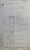
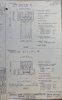
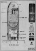
The components and method of filling are shown on A.R.D. Drawing 8074, 4 sheets. The drawings incorporate corrections to preliminary reports from other sources.

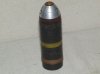
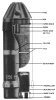
The round consists of a shell body divided by a septum into forward and rear cavities for the explosive and propellant charges, and fitted with a snub-nose percussion fuze of improved design. A standard 20 mm. type gaine is carried by the fuze.

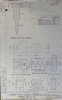
The H.E. filling consists of 51 grammes (average) of T.N.T. in the form of three pre-pressed pellets, in two containers, one cylindrical and one, hemispherical, made from wood pulp paper board.

The propellant consists of 9.8 grammes (average) of a double base propellant, N.C./N.G. = 53.8/41.4, stabilised with diphenylformamide. Use of this stabiliser has not been reported previously.

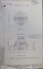
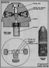
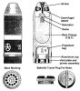
The base of the shell is closed by a steel plug having twelve port holes for emergence of the propellant gases, and housing a small percussion primer in the centre.

The primer filling consists of a gunpowder pellet over a percussion cap of unusual design. A small charge (0.23 grain) of a mercury fulminate/ potassium chlorate/antimony sulphide mixture, in proportions similar to British "A" composition, is pressed into a brass cap shell with a very thin crown (0.007 inch). The cap composition appears to be further sensitised by inclusion of ground glass or similar material. Design tolerances appear to
have been arranged with care to ensure a substantial clearance between the cap composition and the firing anvil.

Firing tests on the pressure bar indicate that the gaine develops greater terminal pressure than the Madsen type, which has a similar contour. The Japanese gaine, however, is considered to be inadequate as applied to ensure detonation of the shell filling.

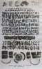
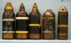
The report includes observations of the effect of one round when fully detonated, against 1/8 in. mild steel plate; also an analysis of the static fragmentation of a further round, together with a photograph of the fragments
(actual size).

The: results of metallurgical examination of the fuze and primer given in the Appendix the Appendix.
 

Attachments

  • Dscf9713.jpg
    Dscf9713.jpg
    97.5 KB · Views: 64
  • Dscf9714.jpg
    Dscf9714.jpg
    95.3 KB · Views: 61
  • Dscf9715.jpg
    Dscf9715.jpg
    94.9 KB · Views: 51
  • Dscf9716.jpg
    Dscf9716.jpg
    95.2 KB · Views: 45
  • Dscf9718.jpg
    Dscf9718.jpg
    96.7 KB · Views: 42
REPORT

Identification


Fuze - Duralumin body, unpainted.
Copper windshield disc under copper retaining washer.
3 screwed side-closing plugs, brass.

Gaine - Issued attached to fuse.
Brass body.
The fuze and gaine, assembled, are wrapped for transit in tycoon paper, sealed with paraffin wax.

Shell - Body (steel) varnished black inside and outside. Overpainted
red band 6 mm. Wide around mouth and yellow band 10 mm. wide, placed 50 mm. below mouth.
Driving-band - corns (unpainted).
Screwed base plug (steel) with 12 holes, varnished black
(including screwthreads).
Brass primer screwed into centre of base-plug.

The filled shell is fitted for transit with a nose-plug of black plastic, embossed * and a tinplate cap over the base. The base cap is held in position by a band of adhesive brown paper wrapped round the shell and cap below the driving band.

The Japanese characters stamped or stencilled on the components are shown on relevant sheets of A.R.D. Drawing 8074.

2. Design

General
Details of the design and method of filling, are shown on A.R.D. Drawing 8074, 4 sheets, attached.

The four rounds examined were closely similar, and information, where restricted to single round, is representative.

The round consists of a shell body, 108 mm. long, divided by an imperforate septum into forward and rear cavities, for the H.E. and propellant charges respectively, and 'fitted with a snub-nosed percussion fuse of new design. A standard 20 mm. type gaine is attached to the fuze.

The rear (propellant) cavity is closed by a steel plug, in which there are 12 port-holes for emergence of the propellant gases

The propellant charge, contained in a silk bag, is ignited by the flash from a small percussion primer, housed in the centre of the steel plug.

The rear of the shell is strengthened to withstand the pressure of the propellant gases by increased thickness of sidewall and by forging the septum to hemispherical contour forward.

The shell is fitted with a single copper rotating band of normal contour.

Components

(i) Fuze and gaine

Details of the assembly are shown on A.R.D. Drawing 8074, sheets 2, 3, 4.

The fuze body (R = 6 cm. approximately) is of unpainted duralumin. The striker is of light alloy and has received protective treatment.
The head of the fuze shows a type of windshield closure not reported previously. The fuze body (head) is undercut to form a shallow projecting flange, which is recessed 0.004 in. deep on the face, to position a copper windshield disc (0.004 in. thickness). The windshield disc is secured by an overlying copper washer, some 0.009 in. thickness, the edge of which is pressed down and inwards under the flange. This closure is made waterproof by liberal application of shellac varnish.

Safety arrangements in the fuze consist of a centrifugal forked bolt, locked in position under a shoulder on the striker, by two smaller centrifugal bolts, positioned in a cross drilling at 90, one bolt on each side. The arrangement represents an improvement to the original design (cf. A.R.D. Explosives Report 90/44, 20 mm. ammunition) which employed the forked bolt only.

The bolts and side-closing plug are of brass, and the centrifugal bolt springs, of steel, blacked. All components show a higher degree of finish than has been observed previously. It is noted that the fuze (and. shell) is dated November, 1943.

The side-closing plugs are set in shellac varnish and are effectively secured under heavy stabbing.

The gaine body and metal components are the standard 20mm. turned reported previously.

(ii) Shell

The shell body is not streamlined end is short in proportion to calibre. The bourrelet is pronounced, above the short parallel of reduced diameter.
The dividing septum is hemispherical towards the H, cavity and flat towards the rear. lie tool marks are visible on the interior of the shell, which has a smooth finish
The steel plug closing the propellant cavity is 8 mm. thick, and is screwthreaded L.H. The port-holes are each 4 mm. diameter and are heavily chamfered at each end. The holes are arranged in a ring and are set parallel to the axis of rotation.

An aluninium retaining cup is placed under the propellant in the propellant cavity. The cup has central hole to avoid impeding flash from the primer. Presumably the cup will also afford additional protection against ingress of moisture.

In transit the tin-plate cover over the base provides protection against moisture and accidental ignition of the primer. The sticky paper by which this is attached is 0.007 - 0-008 in. thick, treated one side with a coumarone type of resin. The cover is removed before firing.

The volume of the propellant cavity, with the base plug in position, is 20.0 c.c. The bagged charge does not fill the cavity. The propellant alone, with bulk density of approximately 0.86gm/cc. occupies not more than 11.5 cc. The nature of the propellant (see Section 3) probably requires this restriction on the amount of charge.

The small primer (A.R.D. Drawing 8074, sheet 4) has a brass body which Screws R.H. into the steel base plug. A central hole through the bottom of the primer body exposes the crown of the percussion cap shell.. The cap shell is of brass andis unusually thin (crown thickness = 0.007 in.). Two convergent fireholes are drilled through the screwed anvil plug security, the cap. The anvil is short and hemispherical, leaving an unusually large gap between it and the surface of the cap composition.
 
The top of the primer body showed evidence of corrosion, presumably caused by the gunpowder filling. This is common to all Japanese primers from small calibre ammunition examined to date.

In all other respects the components were in good condition and in comparison with earlier production of Japanese small calibre cannon ammunition, appear to show considerable improvement in manufacture and assembly technique,

3. Explosive Fillings and Assembly

i) Gaine

The method of filling is shown on the A.R.D. Drawing, sheet 4. The fillings consist of the igniferous cap composition, lead aside pellet, and main filling of RDX. The composition contains a greatly reduced percentage of Mercury fulminate, compared with compositions reported previously. (A.R.D. Explosives Report 90/44, 20 mm. H.E./T.).

The gaines under examination also showed evidence of greater care in assembly. A felt washer had been introduced below the copper of the igniferous cap, presumably to cushion the latter.
 
40mm Caseless

Thanks Tim, excellent info. I will make sure Ken Elks sees it.

Regards
TonyE
 
Tony,

Obviously, I've got a copy of the complete document if required.

TimG
 
Here are a few other drawings and a photo. The 40mm aircraft round is the one on the right.
 

Attachments

  • 40mm HO301 Fuze.jpg
    40mm HO301 Fuze.jpg
    73.7 KB · Views: 28
  • 40mm HO301 section.jpg
    40mm HO301 section.jpg
    66.4 KB · Views: 33
  • 50 and 40mm Jap.jpg
    50 and 40mm Jap.jpg
    96.4 KB · Views: 55
Good info

Tim,
Good info!! Thanks for sharing! Here's a picture of one of these aircraft shells. I don't own this.

Jim
JapaneseOrdnance(at)yahoo.com
 

Attachments

  • ho301.jpg
    ho301.jpg
    78.4 KB · Views: 19
Here is another diagram that hasn't been posted.

Your information is very extensive and interesting TimG. Many thanks for sharing it with us. I would be very interested in a copy of what you have. Do you information of this quality on other Japanese Ordnance?

I will post below the information that I have. Some of it originated from Ken Elks book.
Cheers
BOUGAINVILLE

40 MM HO 301 HIGH EXPLOSIVE PROJECTILE

In 1939 the Army began development of a 40mm aircraft cannon which in 1942 received the designation Ho301. Japanese sources indicated thatfirst attempts used a winged projectile. The following year it was tried out mounted in the wings of a Tojo (Nakajima Ki‑44 Shokei) fighter and proved satisfactory. It was unique among Japanese weapons in that the ammunition for it was of the "rocket" type, propelled by a charge in the base which vents through holes in the base. The duration of this charge is brief and was intended only to fire the projectile from the bore. Muzzle velocity was said to be in the order of 700 feet/second despite attempts made to increase this to 1300 f/s. The rate of fire was 400 rounds per minute.

The only known load of this cartridge is a high explosive typedesignated by the Japanese as Ho301 Howitzer common (Shell). In common with most Japanese ammunition it was transported without fuzes using a bakelite plug instead. The body is virtually straight sided with only a slight bourrelet. Inside there are two cavities the one at the front being rounded at the bottom and containing two cast TNT blocks separated by a wax paper disc, or picric acid and two blocks of T.N.T. In the lower cavity is a charge bag of silk, marked (Ho301) above an aluminium sealing cup. The base is sealed by a screw‑in platedrilled with twelve holes. Into thisplate is screwed a standard Army primer. On firing the aluminium cup is burstby the gases from the charge.

The fuze is a rotor type centrifugally armed. A detent prevents the pin from reaching the detonator. This detent is held in place by two opposing locking detents on springs. As the projectile spins these locks move back against their springs allowing the detent to move back against its spring.

All the examples of this round so far seen are from Osaka Arsenal and are so marked on both projectile and primer. Date of manufacture is almost entirely 1944 (Showa 19) although it most likely continued to the end of the war. Late style markings are the only ones noted, a red band just below the fuze (filled) and a wide yellow one around the centre of gravity (high explosive ‑ high grade steel). There is a waxed paper band just below the drive band, the purpose of which is unknown.

Projectile Dimensions:
Length of projectile (fuzed): 129 mm (5 3/32 inches) fuzed.
Length of projectile (without fuze): 108 mm (4 1/2 inches).
Distance base to rotating band (lower edge): 15 mm (19/32 inch).
Width of rotating band: 8 mm (5/16 inch).
Diameter of rotating band: 41 mm. (1 5/8 inches).
Diameter of body: 39 mm (17/32 inches).
Diameter of bourrelet: 39.5 mm (1 9/16 inches).
Width of bourrelet: 6 mm (1/4 inch).
Distance base to bourrelet (lower edge): 91 mm (3 19/32 inches).
Wall thickness (propellant chamber): 5 mm (13/64 inch).
Wall thickness (H. E. chamber): 4 mm (9/64 inch).

Weights:
Complete round fuzed: 1 pound, 4.7 ounces.
H. E. charge: 2 ounces.
Propellant: 0.4 ounce (10 grams).
Primer: 0.1 ounce.
Fuze, with gaine: 2.1 ounces
Gaine: 0.2 ounce.

Primer Dimensions:
Length: 9 mm (11/32 inch).
Diameter (threads): 12 mm (16/32 inch).
T. P. I: 34 L.H

Weapon in which used: (Ho 301 40 mm air­craft cannon): This is an unusual weapon similar in design to an Oerlikon blow‑back operated cannon, but with the head of the bolt machined as a piston which closes the breech at the forward end of its stroke.

Filling: The filling consists of TNT with a for­ward pellet of picric acid or TNT.

Propellant: The propellant consists of small, greenish‑gray, square flakes of smokeless powder (approximately 1 mm. square) enclosed in a silk bag which is inserted in the after cavity of the projectile. A sealing cup of thin aluminium fits around the after end of the propellant bag and the charge and cup are held in by a perforated base plate which screws (L.H.) into the base of the cavity. The base plate has an outer ring of twelve 3/16 inch holes and a central hole threaded (L.H.) to receive the small flush primer. The aluminium sealing cup is perforated by a single hole in the centre to permit the flash from the primer to reach the propellant. The force of the propellant gases blows through the aluminium cup to open the main series of holes.

Fuze: This is a simple direct‑acting nose fuze with a central axial striker held in the unarmed condition by a slotted safety block, which in turn is held by two spring‑loaded detents.

Remarks: There is also a practice projectile which has the same dimensions and appearance as the H.E. projectile. It is painted black over all and has a nose plug instead of a fuze.
 

Attachments

  • JAPAN ORD 649.jpg
    JAPAN ORD 649.jpg
    82.8 KB · Views: 16
  • JAPAN ORD 443.jpg
    JAPAN ORD 443.jpg
    62.3 KB · Views: 15
Top