Cutaway model of a US WW2 booby trap device, consisting of a Mk2 Handgrenade body with a ‘Firing device Pull/release M3’ screwed in.
The body of the M3 is a cast zinc pipe, threaded at the base to receive the plug with the firing cap in top and the detonator crimped over the tube at the base. About one centimeter below the top of the fuze body, a recess of about two mm wide is machined (PIct 02). In the top of the body a flanged pipe (pict 02 & 04) is roll crimped in place; this pipe has a longitudal slot machined to allow the radial arming and set pin (pict 03, with string) to be removed after installing the booby trap.
The brass firing pin has four longitudal slots at the back end and is also wider at the back end. The steel release and ratched pin has a recess just behind the part that is stuck into the back end of the firing pin. If the firing pin is placed into the body with the release pin in it’s back side and as long as the part marked with a green line (pict 03) is placed in the reces in the fuze body, it pushes the four segments of the firing pin inwards , locking up the end of the release pin, fixating the assembly.
Installing the booby trap is done as follows: The grenade either the fuze is fixated, after which the trip wire is connected; on the near end it is placed in the ratchet, on the far end it is tied to a fixed object. One now starts to slowly wind up the wire in the ratchet until one sees the arming pin start moving backward, tensioning the trip wire. When the firing pin is moved backward so far that the back end of the firing pin (marked with the green line) is placed halfway in the recess, one can remove the radial arming pin carefully. After that , the second safety pin between the firing pin and the firing cap is removed, rendering the booby trap live.
If a person walks against the trip wire, the wire will be tensioned up to the moment the firing pin and release pin are pulled back so far that the smaller diameter part of the firing pin falls in the recess, allowing the steel release and ratchet pin to escape the back end of the firing pin. The firing pin will now be launcched forward by the firing pin spring into the firing cap, initiating the detonator and the grenade body.
If someone observes the trip wire and cuts it, the firing pin spring will move the firing pin with the release pin forward until the part marked with the green line has passed the recess, allowing the release pin to escape the back end of the firing pin which will ignite the firing cap, the detonator and the main charge.
Regards, DJH
Attachments
-
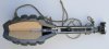 Pict 01 - Booby trap Mk2 with firing device pul-release No.3.jpg290.9 KB · Views: 42
 -
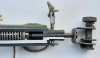 Pict 02 - detail firing device pul-release No.3.jpg184.6 KB · Views: 36
 -
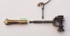 Pict 03 - inner parts firing device pul-release No.3.jpg117.9 KB · Views: 34
 -
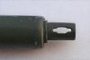 Pict 04 - adjustment slot pull release.jpg149.8 KB · Views: 32