Bonnex,
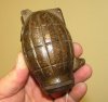
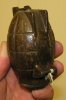
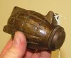
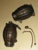
Thanks for the great information on this grenade. Although I could not find an illustration in the patent drawings that was exactly like the grenade in question, it sure appears to be in the same family with the large upper hole to accomodate the impact fuze mechanism.
Do you have any additional information regarding the lower pivot point casting on the body? I'm guessing there might have been overlapping safety levers, one pivoting from the bottom and one from the top, and both under tension from the spring pressure of the fuze mechanism pushing upward. Correct? Thanks again.