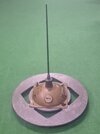
De PDM-1M mine is meant as a blast mine against landing crafts, amphibious vehicles, small vessels and ships and is laid along beaches, in bays, in lakes and rivers. The mine is typicaly laid in water depths between 1,2 to 1,5 meters with a current not higher than 1,5 mtrs/sec. The minimal distance between two mines is to be 6 meters.
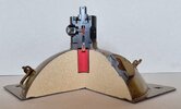
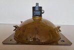
The mine body consists of a square 3mm thick steel plate, 380 x 380 mm, to which a hemispherical steel case of 360 mm diameter and 120mm high is welded. On top of this hemisphere an internally threaded steel ring is welded, which receives the VPDM-1M fuze. To the inside of the ring a thin sheet metal cup is brassed housing the booster charge (red). The full height of the mine body is 140mm. In the corners of the square baseplate a hole is drilled to bolt the mine to the ballast plate with wing nuts.
In the side of the hemispherical mine body a ring with a plug is welded in plase, acting as the filler plug. The mine is filled with 10 Kg of TNT.
The fuze used on the mine is the VPDM-1M tilt fuze. A 685mm long fuze extender is screwed to the tilter on top of the fuze, secured with a split pin.
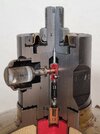
Description and funtioning of the fuze:
The fuze consitsts of a fuze body (1) with a tilter (2) in top. A brass cap (3) is placed over the tilter, secured with a threaded ring (4) on the outer circumfrernce, and a nut (5) on the inside.
A thin steel (3mm dia) threaded rod is screwed into the base of the tilter, the other side connected to the release bolt (6). The release bolt has two through holes; the upper hole houses a thin copper pipe (7), which houses a springloaded (8) safety pin (9), the lower hole houses two steel balls that fall into a groove in top of the springloaded firing pin (11), and are kept in inward position by the housing (12) for the MD-10 duplex detonator (13), keeping the firing pin fixated in tensioned position. The springloaded (8) safety pin (9) is kept in inward position by a steel distance piece while in storage and during transport. When making the mines ready for placement the cup on the side of the mine is unscrewed, the distance piece is removed and replaced with a sugar piece (10).
Just prior to placing the mine in the water, a soft brassed metal strip is pulled away from the circumference of the cup, revealing four small holes that allow water to reach the sugar piece. In 30 degees Celsius water the sugar piece will dissolve in 8 minutes, in 0 degrees water it will take 2,5 hours. With the sugar dissolved the spring (8) loaded safety pin (9) will move outward, arming the mine, leaving the thin copper pipe (7) in place as a firing resistance , together with the deformation of the brass cap (3). The fuze is activated when a sideways force of between 18 to 26 kg is applied to the tip of the extender and the extender is tilted 15 degrees. This will also rotate the tilter (2) 15 degrees, lifting the release bolt (6) upward, allowing the two steel balls to move outward from the detonator housing (12), releasing the firing pin (11) to move into the duplex detonator (13), detonating the mine.
As the loose mine body will tilt when force is applied to the fuze extender due to the torque, the mine is mounted on a heavy cast iron ring which prevents the mine from tilting when force is applied to the extension rod.
The ballast plate is a one piece cast iron ring;
Diameter ballast plate : 800 mm
Thickness ballast plate : 16 mm
Thickness ballast plate i.w.o pins : 70 mm
Weight ballast plate : 39 Kg.
Regards, DJH
The mine body consists of a square 3mm thick steel plate, 380 x 380 mm, to which a hemispherical steel case of 360 mm diameter and 120mm high is welded. On top of this hemisphere an internally threaded steel ring is welded, which receives the VPDM-1M fuze. To the inside of the ring a thin sheet metal cup is brassed housing the booster charge (red). The full height of the mine body is 140mm. In the corners of the square baseplate a hole is drilled to bolt the mine to the ballast plate with wing nuts.
In the side of the hemispherical mine body a ring with a plug is welded in plase, acting as the filler plug. The mine is filled with 10 Kg of TNT.
The fuze used on the mine is the VPDM-1M tilt fuze. A 685mm long fuze extender is screwed to the tilter on top of the fuze, secured with a split pin.
Description and funtioning of the fuze:
The fuze consitsts of a fuze body (1) with a tilter (2) in top. A brass cap (3) is placed over the tilter, secured with a threaded ring (4) on the outer circumfrernce, and a nut (5) on the inside.
A thin steel (3mm dia) threaded rod is screwed into the base of the tilter, the other side connected to the release bolt (6). The release bolt has two through holes; the upper hole houses a thin copper pipe (7), which houses a springloaded (8) safety pin (9), the lower hole houses two steel balls that fall into a groove in top of the springloaded firing pin (11), and are kept in inward position by the housing (12) for the MD-10 duplex detonator (13), keeping the firing pin fixated in tensioned position. The springloaded (8) safety pin (9) is kept in inward position by a steel distance piece while in storage and during transport. When making the mines ready for placement the cup on the side of the mine is unscrewed, the distance piece is removed and replaced with a sugar piece (10).
Just prior to placing the mine in the water, a soft brassed metal strip is pulled away from the circumference of the cup, revealing four small holes that allow water to reach the sugar piece. In 30 degees Celsius water the sugar piece will dissolve in 8 minutes, in 0 degrees water it will take 2,5 hours. With the sugar dissolved the spring (8) loaded safety pin (9) will move outward, arming the mine, leaving the thin copper pipe (7) in place as a firing resistance , together with the deformation of the brass cap (3). The fuze is activated when a sideways force of between 18 to 26 kg is applied to the tip of the extender and the extender is tilted 15 degrees. This will also rotate the tilter (2) 15 degrees, lifting the release bolt (6) upward, allowing the two steel balls to move outward from the detonator housing (12), releasing the firing pin (11) to move into the duplex detonator (13), detonating the mine.
As the loose mine body will tilt when force is applied to the fuze extender due to the torque, the mine is mounted on a heavy cast iron ring which prevents the mine from tilting when force is applied to the extension rod.
The ballast plate is a one piece cast iron ring;
Diameter ballast plate : 800 mm
Thickness ballast plate : 16 mm
Thickness ballast plate i.w.o pins : 70 mm
Weight ballast plate : 39 Kg.
Regards, DJH
Attachments
-
 01 - PDM-1M mine with footplate.jpg1 MB · Views: 44
 -
 02 - PDM-1M mine cutaway model.jpg809.2 KB · Views: 42
 -
 03 - PDM-1M mine.jpg694.4 KB · Views: 44
 -
 04 - VPDM-1M tilt rod fuze with numbers.jpg878 KB · Views: 44
 -
05 - Footplate and antenna PDM-1 M mine.pdf273.9 KB · Views: 7
-
 06 - PDM-1M op X.jpg212.5 KB · Views: 44
Last edited: