What's new
British Ordnance Collectors Network

This is a sample guest message. Register a free account today to become a member! Once signed in, you'll be able to participate on this site by adding your own topics and posts, as well as connect with other members through your own private inbox!

Question about igniters for no.15 and no.16 grenades

ewag2

Well-Known Member
Premium Member
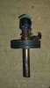
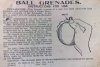
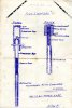
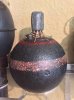
I recently picked up a couple of reproduction Brock igniters to display with my no. 15 and no. 16 grenades. I have seen them set up differently in different pictures and I am wondering what the correct way to attach them is. I have seen them pushed all the way in, up to the head and other times with a length of the time fuze sticking out. Also, I have seen the no. 15 with a short length of copper det tube sticking out that the fuze inserts into, and other times not. Examples of the variances can be seen in these links:

http://www.lexpev.nl/grenades/europe/unitedkingdom/no15.html

http://www.lexpev.nl/grenades/europe/unitedkingdom/no16.html


What is the correct way to do this? Is there more than one way? If so, what is the reason for the difference? I would like to display them as historically accurate as possible. I can pick up some copper tubing at a hobby store if that is needed to complete the no. 15, but I won't bother if I don't need to. Any help would be appreciated.
 
Rob . They push all the way in otherwise they'd flop about when you tried to ignite them with a brazzard . There's a thread on this with pictures somewhere on the site that you might find with a search . Mike.
 
Rob . They push all the way in otherwise they'd flop about when you tried to ignite them with a brazzard . There's a thread on this with pictures somewhere on the site that you might find with a search . Mike.

Thanks, Mike. This certainly makes sense! It's odd that I've a few no.15s over the years that had the copper tube protruding from the body. I guess someone must have just pushed the det tube out a bit for some reason.

Rob
 
I think the copper tube protruded about 1/4 inch as there was a screw in the No 15 plug that allowed the det to be fastened with a wire. So almost fully inserted is probably more accurate.

John
 
I think the copper tube protruded about 1/4 inch as there was a screw in the No 15 plug that allowed the det to be fastened with a wire. So almost fully inserted is probably more accurate.

John

So for the no.15 I should add some copper tubing, but for the no.16 I should shove the fuse all the way in?
 
mvc-170s.jpgmvc-171s.jpg
Rob . No . In my experience the ones with a protruding piece of copper tube are probably drills & the bit sticking out is there just to represent a fuze . The normal HE version has a flush det. holder [see pics] so the fuze would be pushed all the way in . Of course , I just missed WW1 so there could be another explanation & I would be happy to hear about it . Mike .
 
Thanks again, Mike. This also makes sense. I have never seen a no.16 with the tube protruding. I have only seen it on no.15s and I see no reason why there should be a difference between how the two are set up. I assume I have seen this on no.15s only because I have seen so many more of those than no.16s. Rob
 
Yesterday, Mike took me through this in person and I agree with his logic and experience. I think what has perhaps confused my position is that many museums exhibit these grenades differently and probably incorrectly. I take as an example two from the IWM shown in Skennerton's Grenade book.

John

SSCN2840.JPG
 
The Brock fuze for the No.15 hand grenade comprised a match composition igniter, a length of four second fuze and a No.6 detonator. Since the safety fuze burned at a rate of approximately 1ft (30cm) in 30 seconds, the fuze length therefore had to be 4cm, from the match composition to where it met the mercury fulminate inside the detonator tube. The drawing of the Brock lighter shows the wood terminating cap with safety fuze embedded within.

The attached instructions for the Ball should be self-evident as to how the grenade was used, but about 1.5cm of safety fuze protruded from the top of the grenade which was then secured with copper wire to the body plug. This is illustrated in the drill fuze shown (ex Aldershot Bombing School, 1919), although the physical construction differs from that of the service fuze; the drill item utilises a length of copper tube/dummy detonator which locates fully into the grenade detonator sleeve and also protrudes from the body plug by the nominal 1.5cm.

When after the battle of Loos the Ball grenades were withdrawn as hand grenades, they were retained as catapult grenades, with the 4s fuzes replaced by 9s fuzes, viz:

"There are a large number of catapults at the Front both in France and Gallipoli. The ammunition for these is not adequate, but we now have got ready the following which should meet the case and we are prepared to supply in quantity:- (a) Ball grenades prepared with long fuzes especially for use with catapults. Supply 100,000 per week. At the proportions laid down 3/4 should go to France and 1/4 to Gallipoli..." Director General, TW Supplies, 4/11/15.

This latter use of the grenade with long fuze is likely the reason for confusion in drawings and in museum displays.


Tom.
 

Attachments

  • No.15 igniter, drill.jpg
    No.15 igniter, drill.jpg
    98.5 KB · Views: 51
  • Ball Instructions.jpg
    Ball Instructions.jpg
    203.5 KB · Views: 51
  • Igniters.jpg
    Igniters.jpg
    68.9 KB · Views: 52
Thanks, Tom. This was very informative and seems to settle the matter.

I also noted from your images that the wire for holding the fuze in place should be copper. I have seen steel wire used used, but I don't think it was original. Was steel sometimes used instead?

Some no.15s have a screw to attach the wire, but some just have a protrusion cast onto the plug. The version with the screw seems to be less common. Does anyone know the reason for the difference in construction? I'm guessing it's because the one without the screw was simpler to make, but perhaps someone here knows more about it. Rob
 
And then when you used a No15 configured for a catapult as a hand grenade, you have to cook it off. Must have been quite intimidating ...
 

Attachments

  • image.jpeg
    image.jpeg
    170.2 KB · Views: 35
My No15. w/ my homemade fuse. The cooper tube wouldn't push all the way down vet easily do I left too much showing I think. Good thread BTW!
 

Attachments

  • image.jpg
    image.jpg
    292.5 KB · Views: 28
Top