Evening all,
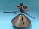
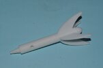
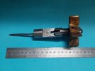
Just though I'll share the restoration performed for a War Nose Mk V torpedo pistol.
(Refer to: https://www.bocn.co.uk/threads/war-nose-mk-v.108474/)
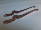
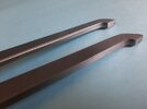
The item was unfortunately missing both the contact levers (whiskers) and the safety pin - I'll just be focusing on the replacement whiskers as the safety pin was simply made using a suitable off the shelf stainless steel Eye bolt and machined down to the correct pin diameter required.
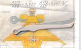
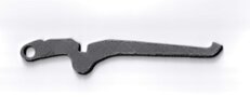
The whiskers were more challenging as the only reference I had was the following cross-sectional diagram:
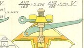
Bear in mind that the above diagram only highlights one of the whisker type required - the other identical two are different base on how they intersect with the striker mechanism:
1st Attempt:
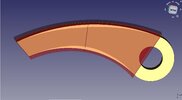
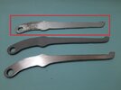
The first attempt (old school) method) was to use a 3mm thick aluminium rectangle bar and trace /cut out the adjusted size diagram on top............
Caveat No.1: The diagram is exactly that - a diagram, not a technical drawing to scale _ refer to red highlighted top prototype below:
(the ones below are closer to the final whisker shape after many iterations)
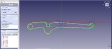
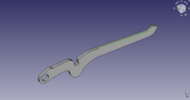
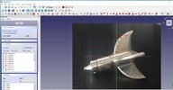
The realization that numerous small fine adjustments were going to be required in order to fine-tune the prototype(s) - the most efficient process was to use a 3D CAD program and "print" ABS plastic ones for relatively low cost, ease of adjustment etc.
The 3D application used was FreeCAD - an open source 3D program that has the same functional characteristics as Auto CAD (expensive $$$) - and as the App name implied - free!!!
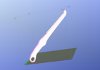
The file is then sent to the 3D printer - in this case an UP+2 3D printer:
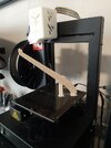
It takes between approx. 1 to 2 hrs to print each prototype (longer if the 3D filament jams in the printer head etc )
)
The cross whiskers - not shown in the diagram are different around where the whiskers perform the mechanical cam action in the striker. Further, the x2 cross whiskers must permit the insertion through the striker in order to allow all whiskers to mechanically CAM when downward pressure is applied:
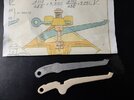
Note the "U" shape notch in the design of the x2 cross whiskers (bottom whisker)
Precise adjustments could not really be calculated due to the difficulty in gaining access through the pistol's body whisker slot, so many "iterations" were done: (yep - guesstimates by mm)
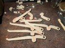
Must have gone through a whole roll of ABS plastic!!! LOL
Caveat No 2: - 3d printing
The whole purpose of using 3D printing was to:
1) Produce working ABS plastic prototypes;
2) Sent the 3d file (.STL) to a commercial 3D Metal printer for the final product.
However, there are two issue with the above:
1) 3D printing is expensive to produce a couple of objects - of course cheaper if mass numbers were going to be produced. The above whiskers (x3) were around
> Stainless Steel (SS316) $350
> FIne polishing $750
> Mild Steel (MS1) $610
> Fine polishing not available for the MS ones
2) The initial 3D SS metal object is far from ideal - meaning that further work is required - i.e. fine polishing
This is typical of a SS 3D metal print prior to fine polishing:
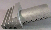
Obviously does require the fine polishing to look half decent!
The other option for consideration was to use a waterjet cut method - somewhat cheaper but the danger here is that it is effectively changing a 3D object back to 2D.
The 3D .STL files are converted to .DXF files for the waterjet application.
Caveat No3: Waterjet cuts are based on available off the shelf steel stock - typically, either a 4mm or 5mm thickness sheet
The whiskers 3D required thickness was 4.6mm - so I ended up selecting the 5mm sheet as I was going to "polish" the MS whiskers myself. Easy right - that's 0.2 mm off each side!
The waterjet whiskers in mild steel (MS) cost approx. $380 and was quite impressed with the result:
(Note - Stainless Steel is harder to polish)
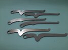
The waterjet whiskers are on the LHS | ABS Plastic on RHS:
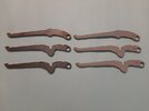
After quite a bit of "polishing" using various grades of wet & dry sandpaper: - continued on next post.........( limited to 10 x photos per post?)
Just though I'll share the restoration performed for a War Nose Mk V torpedo pistol.
(Refer to: https://www.bocn.co.uk/threads/war-nose-mk-v.108474/)
The item was unfortunately missing both the contact levers (whiskers) and the safety pin - I'll just be focusing on the replacement whiskers as the safety pin was simply made using a suitable off the shelf stainless steel Eye bolt and machined down to the correct pin diameter required.
The whiskers were more challenging as the only reference I had was the following cross-sectional diagram:

Bear in mind that the above diagram only highlights one of the whisker type required - the other identical two are different base on how they intersect with the striker mechanism:

1st Attempt:
The first attempt (old school) method) was to use a 3mm thick aluminium rectangle bar and trace /cut out the adjusted size diagram on top............
Caveat No.1: The diagram is exactly that - a diagram, not a technical drawing to scale _ refer to red highlighted top prototype below:
(the ones below are closer to the final whisker shape after many iterations)

The realization that numerous small fine adjustments were going to be required in order to fine-tune the prototype(s) - the most efficient process was to use a 3D CAD program and "print" ABS plastic ones for relatively low cost, ease of adjustment etc.
The 3D application used was FreeCAD - an open source 3D program that has the same functional characteristics as Auto CAD (expensive $$$) - and as the App name implied - free!!!

The file is then sent to the 3D printer - in this case an UP+2 3D printer:

It takes between approx. 1 to 2 hrs to print each prototype (longer if the 3D filament jams in the printer head etc
The cross whiskers - not shown in the diagram are different around where the whiskers perform the mechanical cam action in the striker. Further, the x2 cross whiskers must permit the insertion through the striker in order to allow all whiskers to mechanically CAM when downward pressure is applied:

Note the "U" shape notch in the design of the x2 cross whiskers (bottom whisker)
Precise adjustments could not really be calculated due to the difficulty in gaining access through the pistol's body whisker slot, so many "iterations" were done: (yep - guesstimates by mm)

Must have gone through a whole roll of ABS plastic!!! LOL
Caveat No 2: - 3d printing
The whole purpose of using 3D printing was to:
1) Produce working ABS plastic prototypes;
2) Sent the 3d file (.STL) to a commercial 3D Metal printer for the final product.
However, there are two issue with the above:
1) 3D printing is expensive to produce a couple of objects - of course cheaper if mass numbers were going to be produced. The above whiskers (x3) were around
> Stainless Steel (SS316) $350
> FIne polishing $750
> Mild Steel (MS1) $610
> Fine polishing not available for the MS ones
2) The initial 3D SS metal object is far from ideal - meaning that further work is required - i.e. fine polishing
This is typical of a SS 3D metal print prior to fine polishing:

Obviously does require the fine polishing to look half decent!

The other option for consideration was to use a waterjet cut method - somewhat cheaper but the danger here is that it is effectively changing a 3D object back to 2D.
The 3D .STL files are converted to .DXF files for the waterjet application.
Caveat No3: Waterjet cuts are based on available off the shelf steel stock - typically, either a 4mm or 5mm thickness sheet
The whiskers 3D required thickness was 4.6mm - so I ended up selecting the 5mm sheet as I was going to "polish" the MS whiskers myself. Easy right - that's 0.2 mm off each side!
The waterjet whiskers in mild steel (MS) cost approx. $380 and was quite impressed with the result:
(Note - Stainless Steel is harder to polish)
The waterjet whiskers are on the LHS | ABS Plastic on RHS:

After quite a bit of "polishing" using various grades of wet & dry sandpaper: - continued on next post.........( limited to 10 x photos per post?)
Last edited:

