Description of the S-mine 35
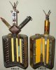
Cutaway model of a S(preng)-mine 35 bounding anti personel mine.
The mine is build up of a cast iron top and bottom flange with a groove and a rim on the outside, locking up two sheet steel pipe pieces, between which a load of bearing balls is placed. The mine is placed in a steel bushing, that serves as an mortar barrel. In the top flange five holes are drilled, the first and largest is the filler plug; three holes at 120 degrees each are used to insert the detonators to arm the mine. The fifth, centerline hole has a threaded piece of pipe sticking out that is hooked behind the lower flange by means of a rim and bolts down the inner parts of the mine by means of a nut on top. The lower part of this pipe contains a 4,5 seconds black powder delay pellet. On top of this threaded pipe a single S.Mi.Z35 can be placed, either a 3 way connection piece, enabeling the use of one pressure fuze on top and two pull igniters on the sides. The lower flange houses a round lead plate, locking up the propelling charge. It is held in place by a steel ring.
The lower flange of the mine is connected to the mortar bushing base by means of three M6 countersunk screws, at 120 degrees each. After ignition of the propelling charge, pressure has to build up to a point where the three screws are broken off. The mine is then free to move up.
The space between mine and mortar bushing at the upper outer rim of the mine is normally closed with weather resistant tape. This to enshure the internal parts of the mine stay dry for a long period.
Operation of the mine: The mine is dug in up to where only the top of the S.Mi.Z35 is protuding out of the ground. If the fuze is activated (21 pounds required for the S.Mi.Z35), the flame travels down the centerline pipe, igniting the 4,5 seconds delay fuze in the lower part (this is done to prevent the mine from not bounding up if a person stands upon it). The black powder propelling charge is ignited, throwing the mine in the air. During the ignition of the propelling charge, the three delay pellets below the detonators are also ignited, delaying explosion of the mine up to between 3 and 5 feet above the ground.
Effective range of the mine is between 150 and 200 yards.
Diameter : 4 inches
Length : 5 inches w/o fuze.
Total weight : 9 pounds
Explosive charge 6,5 ounces of flaked TNT or Amatol.
Coulor : Ocre yellow or field green
Fuzes used : S.Mi.Z..35 , Z.Z.35 , ZZ.42 , Z.U.ZZ 35
An interesting difference in production of these mines can be found in the fact that some mines have brass tubes as detonator housing, some, like the one on this picture have pressed cartboard tubes.
In this case , the mine is filled with rejected bearing balls, sometimes it is filled with the rejected 7,92mm or 9mm Steel cores of S.m.e projectiles.
When used as a pull operated mine, it is laid in a cylindrical hole , held in place by four stakes. Trip wires are attached to the fuzes ans streched out in opposite directions. The wires run four inches above the ground and pass through eye screws fixed to the top of the wooden stakes.
Description of the S-mine 44
Cutaway model of a S(preng)-mine 44 bounding anti personel mine.
The mine is build up of a cast iron top and bottom flange with a groove and a rim on the outside, locking up two sheet steel pipe pieces , between which a load of schrapnell is placed. The mine is placed in a steel bushing, that serves as an mortar barrel. In the top flange three holes in a row are drilled, the first and largest is the filler plug, the centerline hole is used to insert the detonator to arm the mine, the third hole has a threaded piece of pipe sticking out that is pressed into the bottomplate. A nut over the thread bolts the upper and lower flange together.
The threaded pipe piece also contains a expulsion charge with a 4,5 seconds delay pellet on top.
The upper part of the center pipe is made of cartboard and contains the detonator. The lower part is made of steel and contains a firing pin which is held in place by two balls in a recess, whom, on their turn are locked in outward position by a pin. This pin is connected to a steel wire, connected to the steel mortar bushing.
Operation: the mine is dug into the ground up to where only the three antenna of the S.Mi.Z 35 protrude above the ground. If stepped upon (21 ponds required), the striker sleeve is pushed down, up to a moment where the balls that lock the firing pin outward fall in the wider part of the fuze housing, releasing the firing pin. The flame of the firing cap travels down into the delay pellet, giving the mine a 4,5 seconds delay before bounding up (this is done to prevent the mine from not bounding up if a person stands upon it). The black powder pellet is ignited and the mine is thrown upward, until at 2 feet and 10 inches the pin on the wire is pulled away, enabeling the balls to move inward and release the firing pin. The firing pin hits the firing cap (red) exploding the detonator and the main charge.
Effective range of the mine is between 150 and 200 yards.
As the mine explodes about 0,85 mtrs. above the ground and the shrapnell is thrown 360 degr. around, the effect is much greater.
Diameter of the mine : 4 inches
Height : 5 1/ 8 inches
Weight : 8,8 pounds
Coulor : Ocre yellow or field green
Fuzes used : S.Mi.Z..35 , S.Mi.Z.44 , ZZ.42.
In this case, the mine is filled with pieces of cut wire. It can also be loaded with rejected bearing balls. Sometimes, it is filled with rejected 7,92mm or 9mm Steel cores of S.m.e projectiles.
When used as a pull operated mine, it is laid in a cylindrical hole, held in place by four stakes. Trip wires are attached to the fuzes ans streched out in opposite directions. The wires run four inches above the ground and pass through eye screws fixed to the top of the wooden stakes.
Regards DJH