RML Projectiles General Info
These were shot, Palliser shot common shell, Palliser shell, shrapnel case and star. Palliser projectiles, both shot and shell, were cast hollow and closely resembled one another. Designed for the attack of iron-clad ships and masonry, filled shell were not fuzed; the heat generated on impact was sufficient to explode the gunpowder filling.
Early projectiles of all natures except case were fitted with brass or gunmetal studs shaped to run in the grooves of the rifling according to the 'Woolwich' system copied from the French. As they had to be pushed by hand down the bore against accumulated fouling from gunpowder cartridges - and often in a hurry - projectiles had to be loose-fitting. In other words windage had to be generous.
In addition to windage there was 'clearance,' i.e. the space between the height of the stud above the body of the projectile, and the depth of the groove into which that stud fitted.
When a shot or shell was rammed home the studs bore on one side of the groove, and on being fired they bore on the other. The former was called the 'loading edge', and the latter the 'driving edge'. Designers hoped that by inclining the sides of the studs and making the sides of the grooves similar in shape, on firing the studs would have a tendency to run up the sides of the grooves, and so centre the projectile in the bore. The idea was only partially successful.
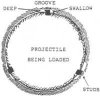
A more positive method of centring was invented by Armstrong who smartly switched to making RML guns in 1864 when his RBL types were no longer wanted. In his 'shunt' system of rifling each groove may be considered as two grooves, a shallow groove towards the driving edge, and a deeper one towards the loading edge. In loading the studs followed the loading edge, keeping in the deep groove, but on coming out bore against the driving edge, shunting into the shallow groove. Thus the projectile was properly centred. The figure shows a section of a shunt bore.
Armstrong's system was adopted for some heavy equipments, notably the RML 7-inch but in 1870 was discontinued, no doubt over expense not only of the composite groove but also the studs which were of pure copper.
From the drawing it will be seen that the studs will be 'shunted' into the shallow grooves, thus centring the projectile.
Pic 1
Section of bore and projectile showing Armstrong's shunt system.
As windage and clearance allowed a significant amount of propellant gas to escape over the RML projectile, RML guns were not as efficient as their RBL equivalents. When the Ordnance Select Committee concerned reported that their RML guns compared favourably with the RBL they did not mention that the former required rather more powder in their cartridges than the latter! Not only did windage and clearance adversely affect the efficiency of the RML gun but the hot, high velocity gases rushing over the projectile caused severe erosion of the bore, particularly in the grooves. This wear greatly exceeded that in RBL equipments. Strange to relate, some of the anti-BL Officers saw the situation as an advantage as it enabled continued use of the old SBML wooden time fuzes initiated by the flash from the propellant charge.
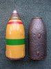
To cut down wear at first a papier mach (moulded paper pulp) gas check was inserted between the cartridge and the base of the shot or shell in the chamber, but in 1878 was replaced by a corrugated copper disc bolted to the base of the projectile as shown in the figure opposite.
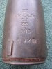
When the gun fired propellant gas pressure tended to flatten the corrugation in the copper disc, thus expanding the rim against the lands and into the grooves of the rifling. On some of the heavier projectiles, including the one in the figure, the rim of the disc was formed with studs in line with the projectile studs. On projectiles for guns with an increasing twist in the rifling the gas check was permitted to rotate.
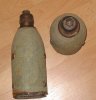
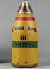
The shell illustrated is of Palliser form, of cast iron with hardened head, a 64-pr intended for use against masonry.
Pic 2
Showing corrugated copper gas check fitted to base of shell.
As might be expected the use of gas checks resulted in a significant increase in muzzle velocities. Then the experts woke up! Gas checks also blocked flash from the propellant charge from reaching the old wooden fuzes still used with common shell and shrapnel. Fire holes had then to be drilled in the rims of gas checks to allow enough flash to reach them. Later it was found that the gas check alone could provide the means of rotating the projectile, so studs were dispensed with. Also, it was realised they did not have to be bolted to the projectile. In some of the very heavy equipments the gas check was loaded separately.
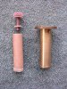
Readers will no doubt have noted the comparatively slow rate of twist in the rifling of RML guns; a faster twist would have sheared the stud off the sides of the projectiles. Hence shot and shell were short; between two and three calibres in length. So-called 'double shell' were slightly longer than the normal but could be used for short ranges only. With heavier guns on sloping platforms a 'wedge wad' had to be loaded after the projectile to prevent it 'setting forward' when the gun came to a sudden stop at the end of runout. Without this precaution a gun was likely to burst on firing. Wedge wads were used with guns of 64-pr and upwards, and were issued in two sizes.
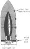
Opposite: A 'wedge wad' consisting of two pieces of wood joined by a piece of cane, loaded immediately after the projectile. Two sizes were issued. The larger in which the wedges measured 7 inches and the cane 7.5 inches was for Guns of 9-inch calibre and upwards. In the smaller the cane was 6.5 ins and the wedges 5.5 inches. It was for guns from 64-pr up to and including 8-inch.
Pic 3
Grommet wads were used in the same manner as wedge wads for smaller guns when required to fire at angles of depression.
Further experiments with gas checks revealed that studs on the rim of the copper disc of the gas check as shown above were unnecessary; that with a simple saucer-shaped gas check, studs on the projectile could be omitted.
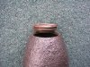
With no studs on the projectile it was possible to revert to a shallow grooved polygroove system of rifling similar to that which Armstrong had pioneered in 1859. Thus in 1875 the 6.3-inch 18-cwt howitzer became the first RML piece to be rifled with a polygroove system, and to be fitted with the new gas check as depicted here.
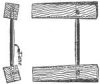
Opposite: Note that the diameter of the shell is more than that of the earlier shell being 6.25 inches, ie windage had been reduced to 0.05 inch. As already stated, although a number of guns were made in 1878 they were not rifled until 1880.
Pic 4
Shell RML 6.3-inch Howitzer Mark 1