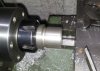
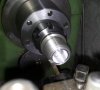
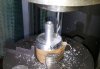
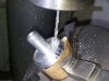
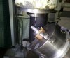
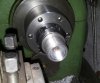
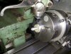
It's more a partly reproduction than a restoration thread but I hope it is still interesting for the members interested in mechanical engineering
Some time ago I asked some questions about the following unknown british fuze in the following thread:
http://www.bocn.co.uk/vbforum/threads/94762-unknown-british-(export-)-fuze
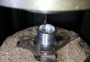
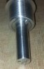
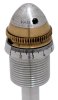
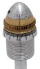
After getting some very useful informations there (thanks again to all involved) I decided to give it a try in making a complete reproduction of the fuze body.
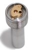
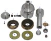
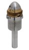
First of all: The photos of the finished project:


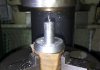
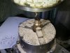
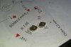
O=Original Part, R=Reproduction

Some time ago I asked some questions about the following unknown british fuze in the following thread:
http://www.bocn.co.uk/vbforum/threads/94762-unknown-british-(export-)-fuze
After getting some very useful informations there (thanks again to all involved) I decided to give it a try in making a complete reproduction of the fuze body.
First of all: The photos of the finished project:
O=Original Part, R=Reproduction
Attachments
Last edited:
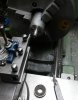
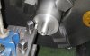
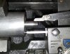
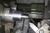
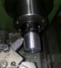

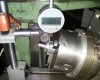
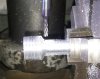
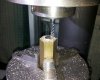
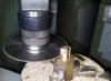
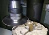
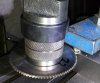
") Such a fuze must have been very expensive because I needed more than a complete weekend to finish. So I guess the production at the Vickers-Armstrong factory was a little bit more efficient.
Such a fuze must have been very expensive because I needed more than a complete weekend to finish. So I guess the production at the Vickers-Armstrong factory was a little bit more efficient.