What's new
British Ordnance Collectors Network

This is a sample guest message. Register a free account today to become a member! Once signed in, you'll be able to participate on this site by adding your own topics and posts, as well as connect with other members through your own private inbox!

anti lifting switch No.12, Britsh, WW2

pzgr40

Well-Known Member
Premium Member
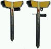
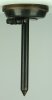
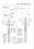
The British WW2 anti lifting switch No.12 was used to boobytrap mines and other items. It consists of two main parts; the upper part is the explosive charge (1), in which the telescope pipe (3) is mounted. In the top of the telescope pipe the duplex detonator (2) is placed. In the lower part of the telescope pipe are the firing pin (6), the firing pin spring (7) and the lock up ring (8 ). The lower part is the nail (5) with the safety fork (4) pressed on, the blocking pin (10),and the spring (9). Functioning of the switch : A hole is dug to place a mine; in the middle of the hole the switch is pressed into the ground, spike down. the mine is placed , making shure there is good contact between the bottom of the mine and the top of the switch. the mine is than covered with soil. The safety pin is now removed with a lanyard, however, if no good contact is made between mine and switch, the upper part will move upward, thereby locking the switch and prevent premature detonation (see fig.5). If the switch makes good contact , the safety pin can easily be removed (see fig.4). The switch is now fully armed. The lower part of the firing pin has a chamfered edge with four machined slots, each at 90 degrees , each 0,7 mm wide effectively changing it into four flexible lips. The firing pin is held in place by the lock up ring that also has an chamfered edge to fit the chamfered edge of the firing pin, and the blocking pin inside the firing pin. As soon as the mine is lifted the spring (9) pushes the upper part upwards, thereby retracting the blocking pin from the firing pin. The firing pin spring pushes the firing pin upwards, thereby forcing the flexible lips to bend inwards, so it can pass the lock up ring. The firing pin will ignite the duplex detonator that will explode the switch. If the mine is lifted more than 15 mm, the switch will explode. Once a switch is armed it cannot be disarmed anymore.

Regards, DJH
 

Attachments

  • Atti lifting switch No.12.jpg
    Atti lifting switch No.12.jpg
    78.3 KB · Views: 54
  • M-anti lift sw. No.12-GB-Wo2-02.JPG
    M-anti lift sw. No.12-GB-Wo2-02.JPG
    100.3 KB · Views: 45
Hallo DJH,
thank you again for your good work. Your description refers to No.'s from 1 to 10. Is there a foto with the numbers missing ?
Regards,
Bellifortis.
 
No, it's a PDF that's too large to be placed here. I'll have to try to make it smaller tomorrow, either the moderator may send me his E-mailadress so I can send it to him and he can override the forum rules concerning file size.
Regards, DJH
 
No, it's a PDF that's too large to be placed here. I'll have to try to make it smaller tomorrow, either the moderator may send me his E-mailadress so I can send it to him and he can override the forum rules concerning file size.
Regards, DJH
Hi DJH,
yeah, I know the problem. It's absolutely frustrating if you write something and then the system tells you that it is too large and all the time spent in writing is for nothing. Good luck in solving that problem.
Bellifortis.
 
Here the drawing with the numbers. Maybe the forum's moderator can add it with the Original posting in top.
Regards, DJH
 

Attachments

  • Switch No.12.jpg
    Switch No.12.jpg
    286.9 KB · Views: 61
Thanks for posting. Was the "nail" (I think No.5 in drawing) the same as the "nail" that formed the basis of Switch, Anti-Personnel No 8?
 
Hallo DJH,
thank you for that nice drawings. By the way, did you make these drawings yourselfes or do you have somebody to do the drawing work. It's an art by itselfes. I don't even know if "technisches Zeichnen" is still a classroom subject with all the modern CAD-devices available. In the old days Siegfried Werner made the best drawings, that we all learned to like.
Regards,
Bellifortis.
Here the drawing with the numbers. Maybe the forum's moderator can add it with the Original posting in top.
Regards, DJH
 
I make these drawings myself by measuring the piece of ammo with a caliper. I am a CAD drawer /work preparer mechanical and steelwerk on a shipyard. These days I prefer the 3D CAD
stuff. I can post some nice 3D stuff if the moderator allows me some more space in MB.
Regards, DJH
 
Switch No.12 Anti-lift - 1.jpg
Here is the Mk1. The only physical difference between the Mk1 and the Mk2 is that the Mk2 Trapping Pin is longer. I do not know the length of either pin.
 
Top