Been re banding my 3 inch 20cwt projectiles with missing bands which have been very successful so far. Managed to master the welding of copper to copper making the banding rings with a gas torch and have been successful crimping them in place. Now i need the correct diameter of the 3inch projectile measured at the bands which so far i have a diameter of 76.2mm which is the diameter of the unbranded projectile, anyone have the correct size at the bands of a banded projectile and a profile how the band is shaped.
British Ordnance Collectors Network
You are using an out of date browser. It may not display this or other websites correctly.
You should upgrade or use an alternative browser.
You should upgrade or use an alternative browser.
3inch 20ctw dimentions
- Thread starter BMG50
- Start date
Been re banding my 3 inch 20cwt projectiles with missing bands which have been very successful so far. Managed to master the welding of copper to copper making the banding rings with a gas torch and have been successful crimping them in place. Now i need the correct diameter of the 3inch projectile measured at the bands which so far i have a diameter of 76.2mm which is the diameter of the unbranded projectile, anyone have the correct size at the bands of a banded projectile and a profile how the band is shaped.
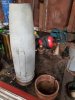
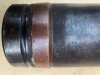
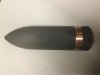
Here's a picture of re-banded 3-inch 20cwt I used to own; unfortunately I don't know if the person who did the re-banding copied the correct profile, but I believe he did. This was from the Woolwich crane ballast box (where I was one of the first on the scene!), many years ago now. Depotman
Last edited:


Darkman
Well-Known Member
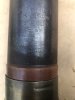
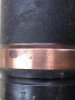
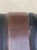
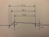
Here are some photos and a sketch of the driveband on my 1940 dated 16lb HE shell.
The chamfer on mine is nowhere near as pronounced as shown in the diagram.
The battery in my digital calipers went flat before I could measure the diameters of the band at top and bottom, but 2mm and 1mm above the shell body is pretty close.
Regards, Graeme
The chamfer on mine is nowhere near as pronounced as shown in the diagram.
The battery in my digital calipers went flat before I could measure the diameters of the band at top and bottom, but 2mm and 1mm above the shell body is pretty close.
Regards, Graeme
Attachments
if I remember right the chap who did the bands Depotman showed, annealed rings and swaged them is using a die and a very big press then turned them similar to those on 12pr which are nominally the same bore. There were a few done by him but I've not got one now.
I made some steel rings which have a inside taper. One ring acting as a support to hold the band in place so the band doesn't slip down past the band grove. do the top first and then taper the other way. the further the steel ring is pushed down the tighter the crimp. It works just the same as hydraulic crimping. I was very surprised when i pushed the copper band down to the band grove that it was quite lose but soon crimped up very tight and took up the slack. I made the bands from 3mm thick copper strip and formed a band and tapered the ends to gas weld using thick electric copper wire as the filler, bit of a knack to it, with a couple of practice welds before. In all after banding up a couple its not as bad as you think.
If you are willing to say, how are you crimping the rings into place?
I have tried doing some 3 Pounders before on a hydraulic hose crimping machine which did work. Unfortunately the machine has since been scrapped.
Annealing very important but this is done when you weld the bands up. Any beating bashing or forming after you need to anneal again.
if I remember right the chap who did the bands Depotman showed, annealed rings and swaged them is using a die and a very big press then turned them similar to those on 12pr which are nominally the same bore. There were a few done by him but I've not got one now.
No flux needed, join two pieces together and form a angle on each end so you have a v grove, support the bottom with a fire brick or cut fire brick to suit. Using metal as a support will act as a heat sink and take longer to heat up. Place a bit of filler wire in the grove and it should melt then the main parts should melt and join. watch the edges as they can get a bit thin. The heat from this process is more than plenty to anneal the band which is very important in the crimping process. Practice makes perfect on a couple of scrap bands.
Darkman
Well-Known Member
I made some steel rings which have a inside taper. One ring acting as a support to hold the band in place so the band doesn't slip down past the band grove. do the top first and then taper the other way. the further the steel ring is pushed down the tighter the crimp. It works just the same as hydraulic crimping. I was very surprised when i pushed the copper band down to the band grove that it was quite lose but soon crimped up very tight and took up the slack. I made the bands from 3mm thick copper strip and formed a band and tapered the ends to gas weld using thick electric copper wire as the filler, bit of a knack to it, with a couple of practice welds before. In all after banding up a couple its not as bad as you think.
I’m having a little trouble visualising this process. I want to have a go at re-banding several shells. Do you have any photos of the steel rings with internal taper, and any of the process being performed? Are you slipping the joined band over the shell then just crimping it a little into the groove, or gas welding the band in situ in the groove? Cheers
Last edited:
I am making the bands first separately to the diameter of the projectile but not the band grove diameter, then sliding the band over the projectile a very nug fit, in line with the grove. You will find that the band becomes loose.
With a formed lathed up steel ring with the inside diameter of the projectile which supports the band in line of the bottom of the grove to the base of the projectile. The top ring the same as the base ring but has a inside taper, the top ring is pushed down to the top band with a very thick bit of steel tubing by a press, i use a large fly press. You push the top ring down and the inside taper of the ring crimps the copper band in the grove and into the sharp grove rings in the band grove, the base ring stoppping the band slipping past the band grove. Then you raise the projectile and swap top tapered ring to facing up to taper the bottom of the band by pushing down on the projectile into the tapered ring thus crimping the rest of the band into the grove.
Dont weld the band up in place the heat is too much plus a un welded band will spring open making it difficult to hold in place to weld. If you still have original paint on the projectile the heat will burn of the markings etc. The method of using pre welded bands for crimping is a cold process, so no heat during the crimping. I will try and get some pictures.
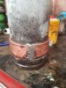
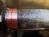
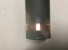
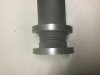
I finished of the band today on the lathe ready to paint up and finish. Some photos and the banding tools.
Attachments
Last edited:
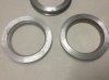
The picture of the rings shows the ring on the left as the support ring which holds the band in aliment to the grove. The rings at the back are packing rings that hold the support ring in place. The right ring is the crimp ring which has a 10 degree taper. The band thickness for 3" which i have used is 3.2 mm x 19 which i had to trim down a little.
I have a copy of drawing No RL 17487C4 which gives details of 3 inch 20 cwt shell's driving band but for some reason the system will not allow me to place it here. Please contact me directly and I will email you a copy.
P.S. the detailed drawing of all British shell up to 1926 is given in my book "British Artillery Ammunition Volume 3 - Quick Fire"
P.S. the detailed drawing of all British shell up to 1926 is given in my book "British Artillery Ammunition Volume 3 - Quick Fire"
rickwedlock
Well-Known Member
i rebanded a 3.7" last week using a slightly different method. i first rolled a 6mm flat bar to the same internal dimension as the band groove then slipped it over the shell into position. once gripped in the vice i soldered the join and the edges, then turned it on the lathe to the correct profile. the joint is still visible but i'm happy with it and the whole process only took a couple of hours