What's new
British Ordnance Collectors Network

This is a sample guest message. Register a free account today to become a member! Once signed in, you'll be able to participate on this site by adding your own topics and posts, as well as connect with other members through your own private inbox!

QF 13-pdr shell dimensions

wingsofwrath

Well-Known Member
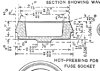
I am trying to make myself 3d-printed QF 13-pdr shrapnel and HE shells to complete my WW1 display.

I have the original fuzes and cartridge casings, so I only need dimensions for the body. Unfortunately, I haven't been able to locate a proper plan, so I had to make do with inaccurate drawings from manuals and pictures, which I then dimensioned from the known calibre, the fuzes and adapters.
I've assumed that both shells have the same overall dimensions and that the driving band is identical to that on the 18-pdr.

Can someone please tell me wherever the plans I came up with are correct? Thank you!

13-pdr plans_800.jpg
 
I've managed to find the dimensions for the 13-Pdr shrapnel for myself, from a 1917 American book named "The Manufacture of Artillery Ammunition" which can be found here, along with dimensions for a lot of other British, French, Russian and even Sebian shells manufactured in the USA during WW1: https://archive.org/details/manufactureofart00alforich

Here they are for those unwilling to trawl through the whole book to find them:

manufactureofart00alforich_Page_755.jpg

Also, I've updated my drawing to incorporate the new dimensions, but I'm still missing the length of the HE shell, so, please, if anybody has one, I'd really like to know the length of the body.

13-pdr plans V2_800.jpg
 
Overall length of the HE shell is exactly 7 & 3/4" (196.85mm). The fuze socket adapter on the shrapnel shell is dimensioned as 1/2" on your drawing, which you have converted to 13.5mm, but 1/2" is 12.7mm. Good luck with your project, I'd love to see the finished results.
Regards, Graeme
 
Thank you!

That is indeed very useful and I'll absolutely post pictures of the finished articles.

Ah. I got the dimension by measuring one of the three genuine adapters I have and it turns out there's a mismach - two of them (one VSM the other unmarked because it's missing it's bottom but probably also VSM because it's really similar with the other one) came out as 1/2 inches or 1.27mm exactly, while the other (marked "BC" - is that "Blackness Castle", or was that only a filling station?) is actually 0.52 inches measured with a tape measure against the surface and 13.5mm measured with my (metric) calipers.

So I guess that means that Vickers Sons & Maxim were really good at machining tight tolerances as per spec while other manufacturers... not so much.

Also, it's interesting to not that in the US plans I posted above the same dimension is given as "0.75 inches".
 
Also, it's interesting to not that in the US plans I posted above the same dimension is given as "0.75 inches".


The 0.75" dimension is from the rim edge of the socket to the inside surface of the base of the socket.

For the 18pr Shrapnel shell, the height of the socket visible when screwed into the shell body is 0.5" (to tolerances H 0.5", L 0.488").

Fuzes, sockets and adapters were made to exacting tolerances, and usually if measured above spec is due to expansion of the metals due to functioning of the fuze/shell.
 
Last edited:
The 0.75" dimension is from the rim edge of the socket to the inside surface of the base of the socket.

Looking more closely at the mess of numbers on that plan it turns out we both might have read it wrong and the "0.75 in" could be the depth of the inside cavity of the adapter, because there's a second dimension on the other side which says "0.6" +/-0.005'" which looks it could be the actual external dimension of the adapter.
Of course, that is still inexplicably bigger than the height of either the specifications or the actual adapters I have and, since we are talking about a plan, I don't think heat deformation can account for this one...

And speaking of heat deformation, in this case we have the opposite problem - the VSM and the unnamed adapter are identical to each other and fit the "per spec dimensions" of 0.5" in height, but the BC adapter is only taller by 0.8mm and it's the exact same diameter of 62mm. So, again, I can't see a mechanical piece heat-deforming in a single direction and an error of less than 1mm can easily be attributable to manufacturing.
 
Last edited:
Looking more closely at the mess of numbers on that plan it turns out we both might have read it wrong and the "0.75 in" could be the depth of the inside cavity of the adapter, because there's a second dimension on the other side which says "0.6" +/-0.005'" which looks it could be the actual external dimension of the adapter.
Of course, that is still inexplicably bigger than the height of either the specifications or the actual adapters I have and, since we are talking about a plan, I don't think heat deformation can account for this one...

And speaking of heat deformation, in this case we have the opposite problem - the VSM and the unnamed adapter are identical to each other and fit the "per spec dimensions" of 0.5" in height, but the BC adapter is only taller by 0.8mm and it's the exact same diameter of 62mm. So, again, I can't see a mechanical piece heat-deforming in a single direction and an error of less than 1mm can easily be attributable to manufacturing.


The 0.75" dimension is from the top edge, or rim, of the socket to the inside surface of the base of the socket, as per the attached image.

The 0.5" dimension is for the 18-pr socket. I don't have a drawing for the 13-pr socket, and it may be different at 0.6".
 

Attachments

  • Socket blank.jpg
    Socket blank.jpg
    77.2 KB · Views: 17
I have the exact same drawing and what you posted here is the blank from which the adapter/socket is machined. You should have posted the one below which shows the finished product, because we are talking about finished dimensions.

18pdrfuze socket_detail.jpg

Anyway, at this point it's clear we are actually saying the exact same thing, we're just using different words to do it. I call the thing an "adapter" which is a more modern appellation, you are calling it "fuze socket" which is what they called it back in the day, but both words describe the same thing.

And we both agree that 0.75 is the inside depth of the adapter/socket, 0.5 is the external for the 18-pdr and 0.6 for either the 13-pdr or simply for the US made 13-pdr for which we have the plans.
 
Last edited:
Here are the finalized drawings. The actual 3d print to follow in the days to come.
The length of the HE shell is indeed 196.85mm, but the dimension lines can't display precision of more than 0.1mm, because the software I'm using is meant for architecture, not high precision engineering, so this will have to do.
Also, I finally went with the dimensions given in the plans for the 13-pdr adapter/fuze socket so 0.6-in instead of 0.5 like that from the 18-pdr. For my shell I'm just going to use my slightly taller adapter, even though it's still a couple of mm shorter than a proper 13-pdr adapter...

13-pdr plans V3_800.jpg
 
As promised, here are the completed shells.

All are 3d-printed except the 18-pdr shrapnel, which is a resin copy cast from an original.
I've used real fuzes for most of them (No.85 Scovill, No.101, No.80 VSM), except on the 18-pdr HE, for which I had originally a No.102 fuze, but it was so deformed in the end I decided to 3d-print myself an No.106 instead.
The markings are based on both manuals and original extant examples and I left the adapter/fuze socket of the No.85 unpainted as it had traces of original paint still on.

Finally, here they are on their casings and in the context of my current collection.

13-18-pdr final_1000.jpg 13-18-pdr final 2_1100.jpg Colectia 10_03_2021_1000.jpg
 
Last edited:
Top