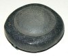
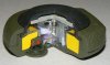
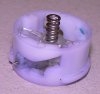
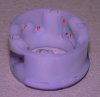
Cutaway model of a SB-33 anti personel mine, The mine's manufacturer was Misar, Italy. These mines were in service in a number of Nato members' armies. It entered service in 1977. the mine has an unique irregular shape that makes visual detection difficult.
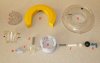
The mine exists of a pvc body in which a transparant plastic ring (G) is placed in which the horseshoe shaped explosive main charge (H) is placed. A locking ring, housing a black rubber pressure cap is screwed upon the body.
As the mine is low metal (only the spring (E) and the firing pin needle (B) are metal), the mine is difficult to detect.
It does not matter if the mine is placed/ scattered with it’s rubber pressure pad facing upward or downward, the mine will function both ways.
As far as I can find out, the SB 33 is watertight up to ten years and does not float.
The rotation ring (D) of the fuze is kept in safe mode by a springloaded radial locking pin (J) in a recess in the rotation ring that is kept in inward position by a rotating key (K)behind it which sticks out of the mine. By rotating this key 90 degrees, it falls out enabeling the radial pin to move outward, making the mine live. If the mine is laid with the helikopter borne SY-AT mine dispensing system –containing 2.496 SB-33 mines- these pins are rotated upon ejection by the dispenser, when hand laid the pin is rotated by hand.
Functioning of the fuze:
When stepped upon:
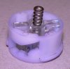
When a person steps on the mine, the pressure is transmitted from the black rubber pressure pad into the cartboard disc below it, into the pressure piston (F), which transmits the force into a spring (E) which rests in a yoke (C). The yoke is locked from radial movement by two longitudal slots that are placed in both the lower fuze housing (A) and the pressure piston (F), fixating the three parts from radial movement from one another. The arms of the yoke rest in two slightly chamfered / sloped recesses (P, approximately 3 degrees) at 180 degrees each in the arming ring (D) forcing the arming ring to rotate when force is applied upon the spring, rotating the arming ring up to the moment where the arms of the yoke fall into the lower slot (Q). Two black arrows point out the position of two notches on the pressure piston (F, see detail picture of notch on right side of it) which fall in the second set of slots a few degrees further (R). With the rotating of the arming ring these notches are forced into the angled open slots (T). The firing pin (B) rests in a slot in the lower fuze housing (A), it’s steel pin rests just below the angled open slot (T). The lower side of the angled slot ends up in a rectangular hole with the size of the front of the firing pin. The upper side of the firing pin (B) is chamfered and a chamfered slot is machined in the stem of the yoke as well. These fit in one another. When the arming ring (D) has rotated far enough (rectangular hole in slot arming ring in front of rectangular front shape firing pin). The chamfered edge of the yoke pressing on the chamfered edge of the firing pin forces the firing pin outward into the firing cap, exploding the mine.
When encountered by explosive mine clearance devices:
When a fuel air explosive is exploded over the ground, the pressure wave will “hit” the rubber pressure pad down rather than the slower pushing movement when stepped upon. This will cause the pressure piston (F) to move down very fast, compressing the spring (E) so fast that it has no time to make the arms of the yoke slide of the slightly chamfered / sloped recesses (P) of the arming ring (D). Within the same moment both notches om the pressure piston (F) fall in the lower part of the (S) of the second set of slots (R). This locks the ring from any rotation. When the spring (E) pushes the pressure pad up again, the mine is functionally again.
Diameter of the mine : 85 mm
Height of the mine : 30mm
Operating pressure : 8 kg
Weight of the mine : 140 gram
Explosives content : 35 gram RDX / HMX (98% / 2%)
The mine can be found in: Afghanistan, Djibouti, the Falkland Islands, Iran, Iraq, Kurdistan, Somalia and the Western Sahara.
The mine was produced by a number of countries, among them: Holland (SB-33), Spain (P-5), Portugal (M/412) and Greece (EM-20). Production however has compleately ceased and European stocks are all destroyed.
The mine can be found in green with a black rubber pressure cap, either fully sand coloured or black. At extra cost the mine can be coated with a special paint that defies detection by infrared sensors.
A SB-33 with an anti handling / disturbance device build below the mine body is called the SB-33/AR. It is mixed in with SB-33 mines to deter mine clearance operations.
Regards, DJH
The mine exists of a pvc body in which a transparant plastic ring (G) is placed in which the horseshoe shaped explosive main charge (H) is placed. A locking ring, housing a black rubber pressure cap is screwed upon the body.
As the mine is low metal (only the spring (E) and the firing pin needle (B) are metal), the mine is difficult to detect.
It does not matter if the mine is placed/ scattered with it’s rubber pressure pad facing upward or downward, the mine will function both ways.
As far as I can find out, the SB 33 is watertight up to ten years and does not float.
The rotation ring (D) of the fuze is kept in safe mode by a springloaded radial locking pin (J) in a recess in the rotation ring that is kept in inward position by a rotating key (K)behind it which sticks out of the mine. By rotating this key 90 degrees, it falls out enabeling the radial pin to move outward, making the mine live. If the mine is laid with the helikopter borne SY-AT mine dispensing system –containing 2.496 SB-33 mines- these pins are rotated upon ejection by the dispenser, when hand laid the pin is rotated by hand.
Functioning of the fuze:
When stepped upon:
When a person steps on the mine, the pressure is transmitted from the black rubber pressure pad into the cartboard disc below it, into the pressure piston (F), which transmits the force into a spring (E) which rests in a yoke (C). The yoke is locked from radial movement by two longitudal slots that are placed in both the lower fuze housing (A) and the pressure piston (F), fixating the three parts from radial movement from one another. The arms of the yoke rest in two slightly chamfered / sloped recesses (P, approximately 3 degrees) at 180 degrees each in the arming ring (D) forcing the arming ring to rotate when force is applied upon the spring, rotating the arming ring up to the moment where the arms of the yoke fall into the lower slot (Q). Two black arrows point out the position of two notches on the pressure piston (F, see detail picture of notch on right side of it) which fall in the second set of slots a few degrees further (R). With the rotating of the arming ring these notches are forced into the angled open slots (T). The firing pin (B) rests in a slot in the lower fuze housing (A), it’s steel pin rests just below the angled open slot (T). The lower side of the angled slot ends up in a rectangular hole with the size of the front of the firing pin. The upper side of the firing pin (B) is chamfered and a chamfered slot is machined in the stem of the yoke as well. These fit in one another. When the arming ring (D) has rotated far enough (rectangular hole in slot arming ring in front of rectangular front shape firing pin). The chamfered edge of the yoke pressing on the chamfered edge of the firing pin forces the firing pin outward into the firing cap, exploding the mine.
When encountered by explosive mine clearance devices:
When a fuel air explosive is exploded over the ground, the pressure wave will “hit” the rubber pressure pad down rather than the slower pushing movement when stepped upon. This will cause the pressure piston (F) to move down very fast, compressing the spring (E) so fast that it has no time to make the arms of the yoke slide of the slightly chamfered / sloped recesses (P) of the arming ring (D). Within the same moment both notches om the pressure piston (F) fall in the lower part of the (S) of the second set of slots (R). This locks the ring from any rotation. When the spring (E) pushes the pressure pad up again, the mine is functionally again.
Diameter of the mine : 85 mm
Height of the mine : 30mm
Operating pressure : 8 kg
Weight of the mine : 140 gram
Explosives content : 35 gram RDX / HMX (98% / 2%)
The mine can be found in: Afghanistan, Djibouti, the Falkland Islands, Iran, Iraq, Kurdistan, Somalia and the Western Sahara.
The mine was produced by a number of countries, among them: Holland (SB-33), Spain (P-5), Portugal (M/412) and Greece (EM-20). Production however has compleately ceased and European stocks are all destroyed.
The mine can be found in green with a black rubber pressure cap, either fully sand coloured or black. At extra cost the mine can be coated with a special paint that defies detection by infrared sensors.
A SB-33 with an anti handling / disturbance device build below the mine body is called the SB-33/AR. It is mixed in with SB-33 mines to deter mine clearance operations.
Regards, DJH
Attachments
-
 01 - SB-33 mechanically functioning dummy mine.JPG131.8 KB · Views: 20
 -
 02 - SB-33 AP mine cutaway model.JPG133.6 KB · Views: 28
 -
 03 - SB-33 inner parts.JPG251.5 KB · Views: 26
 -
 04 - SB-33 Firing pin in safe position.JPG112.4 KB · Views: 17
 -
 05 - SB-33 Firing pin in fired position.JPG120 KB · Views: 15
 -
 06 - SB-33 slots rotation ring.JPG127.6 KB · Views: 15