Here a posting about how to change a 3” (76mm) WW2 M62A1 APC cartridge into a cutaway model.
This may be interesting as a guideline for people who want to change a large caliber projectile into a cutaway model.
I got this projectile at the last collectors meeting, however the base fuze M66A1 as well as the shellcase were missing. Thanks to fellow collectors I was able to obtain these items quite fast and change it to a cartridge cutaway model.
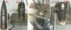
Pict 01;
The projectile as I got it.
Pict 02;
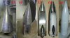
Drawing of the cutting lines on the projectile on a straight table. This enables me to draw a perpendicular line compared to the base of the projectile.
Pict. 03;
Drawing the angle to be cut out –in this case 90 degrees- searching for the center with a flange hook. It is important to make shure both lines are drawn appr. 1 mm on the inside of the true perpendicular lines as to make shure that after cutting the projectile there is enough “meat” left to smoothen (grind) , rasp and polish the projectile without passing over the centerline. After cutting the projectile just a little of the cutting line should be left visible.
With this particular projectile the fuze is the same in all angles cut anywhere around the circumference, so it does not matter where the 90 degrees cut in the projectile is taken out. However when cutting projectiles with more difficult base/nose fuzes – having several side channels at different angles- the fuze has to be cut first. The cut fuze is than places on/in the projectile body, dictating the angle and position of the angle to be cut out.
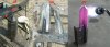
Pict 04;
After placing all cutting lines the projectile is ready to be cut.
It is wise to hatch the part that is going to be cut out. This to make clear which part is going to be cut out and to prevent the mistake of starting to cut on the wrong side of the line.
Pict 05;
Cutting the projectile with a large cutting grinder. One side has been cut.
Pict. 06;
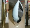
The projectile has been completely cut. To smoothen the surface a small grinder with an abrasive disc is used. During this smoothening one has to continuously check if:
A; one is making the surface straight
B; The surface is perpendicular compared to the straight –table..
Be careful; you can very well cut the entire surface straight to find out the surface is 2 to 3 degrees out of perpendicular. And that’s a lot of grinding.
Pict 07;
Annealing the projectile by heating it up.
Hardening is a process where a piece of red hot steel is cooled down so fast that the carbon has no time to settle between the iron crystal roster and takes in the place of iron atoms. This forms tension in the crystal roster which is called hardness. By heating up the projectile and cooling it down slowly. The carbon can now settle between the iron atoms in the crystal roster so no internal tension occurs in the crystal roster. After cooling down slowly the projectile is now soft. The red hot projectile is placed in a wheelbarrow of fine dry sand, slowing down the cooling down process as much as possible.
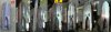
Pict 08;
Het cut and smoothened projectile after cooling down. (appr. 6 hours later)
Pict 09;
Rasping the projectile smooth. To rasp the projectile straight 16 and 14 inch long flat coarse rasps are used. First one side is rasped smooth for about 75%, than the other side is smoothened up to 100%. To prevent the rasp from scratching the smoothened side with the side of the rasp, duct tape is placed over the 100% smoothened side. The last part of rasping is “adding” the centerline “fold”.
Pict 10;
To polish the cutaway surfaces of the projectile I take a strip of P40 sandpaper, folded over the rasp. Keep the sandpaper tensioned between your fingers and “rasp” the projectile until all deep scratches have disappeared. Repeat this with P60 and P80 sandpaper strips. Ensure the movement of the rasp while polishing is pure in the length direction and does not run away sideways as this will be clearly visible as a strange light spot –especially in pictures-.
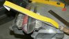
Pict 11;
Finding the centerpoint of the ballistic cap by means of a drill in a lathe.
Pict 12;
Drawing the cutting lines on the ballistic cap. This by placing a strip of sand paper between the cutaway surface and the nose center. This strip is fixated by means of duct tape. By looking from above along the perpendicular line of the projectile and moving the strip of sandpaper fore- and backward a straight line can be found.
Pict 13/14;
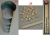
The base fuze BD M66A1before and after setting cutting lines, sawing , rasping and polishing. The driving belt has also been polished.
Pict. 15;
The projectile is masking taped for spray painting, zinc primer is used.
Hours used:
-Drawing cutting lines: 1,5 hours
-Cutting; transport, set up workbench, grinding, smoothening, clean up : 3 hours
-Heating up: rent blowtorch, transport (2x) heating up: 3 hours
-Rasping smooth and polishing : 4 hours
-Drawing cutting line and sawing , rasping and smoothening ballistic cap : 1 hour
-Drawing cutting line and sawing , rasping and smoothening base fuze : 2 hours
-Machine, cut an polish missing internal parts in booster housing –firing cap housing, delay pellet, detonator housing- : 5 hours
-Draw cutting lines , saw , rasp and polish he shellcase and the primer + magazine : 2,5 hours
-Finishing internal parts fuze + sandpapered templates explosive charge in projectile : 3 hours
-Making dummy main charge and magazine charge in shellcase : 3 hours
-Drilling holes for blind rivets : 1 hour
-Painting the outside of the projectile : 0,25 hours
-Final polish just before adding transparent varnish layer : 1 hour
-Spraying varnish: 0,5 hours.
So, in total it cost me 30,75 hours to -working with normal speed- cut this cartridge. However , the works were carried out spread over a month.
This may be interesting as a guideline for people who want to change a large caliber projectile into a cutaway model.
I got this projectile at the last collectors meeting, however the base fuze M66A1 as well as the shellcase were missing. Thanks to fellow collectors I was able to obtain these items quite fast and change it to a cartridge cutaway model.
Pict 01;
The projectile as I got it.
Pict 02;
Drawing of the cutting lines on the projectile on a straight table. This enables me to draw a perpendicular line compared to the base of the projectile.
Pict. 03;
Drawing the angle to be cut out –in this case 90 degrees- searching for the center with a flange hook. It is important to make shure both lines are drawn appr. 1 mm on the inside of the true perpendicular lines as to make shure that after cutting the projectile there is enough “meat” left to smoothen (grind) , rasp and polish the projectile without passing over the centerline. After cutting the projectile just a little of the cutting line should be left visible.
With this particular projectile the fuze is the same in all angles cut anywhere around the circumference, so it does not matter where the 90 degrees cut in the projectile is taken out. However when cutting projectiles with more difficult base/nose fuzes – having several side channels at different angles- the fuze has to be cut first. The cut fuze is than places on/in the projectile body, dictating the angle and position of the angle to be cut out.
Pict 04;
After placing all cutting lines the projectile is ready to be cut.
It is wise to hatch the part that is going to be cut out. This to make clear which part is going to be cut out and to prevent the mistake of starting to cut on the wrong side of the line.
Pict 05;
Cutting the projectile with a large cutting grinder. One side has been cut.
Pict. 06;
The projectile has been completely cut. To smoothen the surface a small grinder with an abrasive disc is used. During this smoothening one has to continuously check if:
A; one is making the surface straight
B; The surface is perpendicular compared to the straight –table..
Be careful; you can very well cut the entire surface straight to find out the surface is 2 to 3 degrees out of perpendicular. And that’s a lot of grinding.
Pict 07;
Annealing the projectile by heating it up.
Hardening is a process where a piece of red hot steel is cooled down so fast that the carbon has no time to settle between the iron crystal roster and takes in the place of iron atoms. This forms tension in the crystal roster which is called hardness. By heating up the projectile and cooling it down slowly. The carbon can now settle between the iron atoms in the crystal roster so no internal tension occurs in the crystal roster. After cooling down slowly the projectile is now soft. The red hot projectile is placed in a wheelbarrow of fine dry sand, slowing down the cooling down process as much as possible.
Pict 08;
Het cut and smoothened projectile after cooling down. (appr. 6 hours later)
Pict 09;
Rasping the projectile smooth. To rasp the projectile straight 16 and 14 inch long flat coarse rasps are used. First one side is rasped smooth for about 75%, than the other side is smoothened up to 100%. To prevent the rasp from scratching the smoothened side with the side of the rasp, duct tape is placed over the 100% smoothened side. The last part of rasping is “adding” the centerline “fold”.
Pict 10;
To polish the cutaway surfaces of the projectile I take a strip of P40 sandpaper, folded over the rasp. Keep the sandpaper tensioned between your fingers and “rasp” the projectile until all deep scratches have disappeared. Repeat this with P60 and P80 sandpaper strips. Ensure the movement of the rasp while polishing is pure in the length direction and does not run away sideways as this will be clearly visible as a strange light spot –especially in pictures-.
Pict 11;
Finding the centerpoint of the ballistic cap by means of a drill in a lathe.
Pict 12;
Drawing the cutting lines on the ballistic cap. This by placing a strip of sand paper between the cutaway surface and the nose center. This strip is fixated by means of duct tape. By looking from above along the perpendicular line of the projectile and moving the strip of sandpaper fore- and backward a straight line can be found.
Pict 13/14;
The base fuze BD M66A1before and after setting cutting lines, sawing , rasping and polishing. The driving belt has also been polished.
Pict. 15;
The projectile is masking taped for spray painting, zinc primer is used.
Hours used:
-Drawing cutting lines: 1,5 hours
-Cutting; transport, set up workbench, grinding, smoothening, clean up : 3 hours
-Heating up: rent blowtorch, transport (2x) heating up: 3 hours
-Rasping smooth and polishing : 4 hours
-Drawing cutting line and sawing , rasping and smoothening ballistic cap : 1 hour
-Drawing cutting line and sawing , rasping and smoothening base fuze : 2 hours
-Machine, cut an polish missing internal parts in booster housing –firing cap housing, delay pellet, detonator housing- : 5 hours
-Draw cutting lines , saw , rasp and polish he shellcase and the primer + magazine : 2,5 hours
-Finishing internal parts fuze + sandpapered templates explosive charge in projectile : 3 hours
-Making dummy main charge and magazine charge in shellcase : 3 hours
-Drilling holes for blind rivets : 1 hour
-Painting the outside of the projectile : 0,25 hours
-Final polish just before adding transparent varnish layer : 1 hour
-Spraying varnish: 0,5 hours.
So, in total it cost me 30,75 hours to -working with normal speed- cut this cartridge. However , the works were carried out spread over a month.
Attachments
-
 01 - drawing cutting lines, 1 tm 4.JPG99.3 KB · Views: 73
 -
 02 - cutting and heating, 5 tm 7.JPG112.4 KB · Views: 64
 -
 03 - rasping & polishing, 8 tm 9.JPG157.6 KB · Views: 61
 -
 04 - Polishing methotology, 10.JPG108.5 KB · Views: 58
 -
 05 - ballistic cap, fuze and paintwork 11 tm 15.JPG99.5 KB · Views: 67
 -
 06 - cutting lines on shellcase and straghtness check, 16 tm 18.JPG155.5 KB · Views: 59
 -
 07 - filling shellcase 19 tm 21.JPG98.9 KB · Views: 58
 -
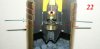 08 - rivetting projectile on shellcase 22.JPG77.9 KB · Views: 56
Last edited: