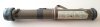
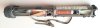
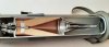
Cutaway model of a RPG-75 recoiless anti tank launcher. This weapon was designed in Czechoslovakia in the 70’s of the last century as a light and disposable single use anti tank weapon. However, as the US counterpart the 66mm LAW used a rocket, the RPG-75 used the recoiless gun principle.
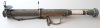
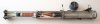
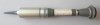
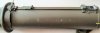
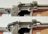
The RPG-75 (pict 1 to 4) consists of an aluminium tube in which a recoiless cartridge (pict.05) is placed. The cartridge is fixated in the pipe by means of a bayonet mount which is placed in the backside of the aluminium pipe. The counterparts of the bayonet fitting are placed on both the forward part of the aluminium nosecap of the pressure chamber and the outside of the aft part of the venturi. To make the RPG-75 ready for use the aluminium pipe is taken in one hand, and the other hand grips the flange of the venturi. The venturi is rotated 30 degrees counterclockwise to release it form the bayonet mount, the cartridge is pulled backward and telescoped out, and the venturi is rotated 30 degrees clockwase to lock the forward bayonet mount. By locking the bayonet mount in the forward position, the firing cap of the motor is placed in line of the firing pin. (pict 08).
The cartridge (pict. 05) consists of a shaped charge with a PIBD (Point Ignited Base Detonated ) fuze , also called a spit back fuze. The steel housing of the nose part of the fuze forms the stand off; the optimum distance between the cone and the target to archieve maximum target penetration. The inside of the nose part of the fuze houses a impact fuze with a zig-zag delay safety mechanism with an impact detonator in the forward part and a flame sensitive detonator at the base. Upon impact the impact detonator is ignited, the flame travels down into the flame sensitive detonator and the flame of this detonator travels downward through the ccone into the base part of the fuze.
This base part of the fuze is kept out of line with the booster charge penthrite (pink) when safe. Upon firing, inertia releases the flame sensitive lower detonator, which is moved forward into the armed position by a spring.
Behind this flame sensitive lower detonator, a hollow screw with a pyrotechnic delay fuze is screwed into the base of the fuze; if the target is missed, it will ignite the flame sensitive lower detonator in between 3 to 6 seconds. This is the self destruct mechanism.
A wave shaper (white) is placed in the explosive charge; this forces the detonation wave is a more favorable shape before reaching the cone, enhancing the armour penetration between 10 to 15%.
The warhead is connected to the motor by means of yoke shaped steel bushing with a hole in the center. A radial placed screw is screwed through both yokes, both screws having a dowel at the inward facing end. Both these dowels are placed in opposite radial holes drilled in the outside of the lower fuze housing, fixating the warhead to the motor.
The yoke shaped bushing is bolted into the aluminium top flange of the motor, which also houses the firing cap to ignite the propelling charge . A hard and tough steel pipe is screwed into the base of the top flange, forming the combustion chamber. The venturi is screwed into the base of the steel pipe. Above the venturi , a cone shaped grid is placed to enshure no half- or unburned powdersticks will leave the combusion chamber.
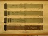
The powdercharge consists of a bundle of 3,5 mm diameter and 180mm long perforated sticks with a bag of black powder sewed to the top top enshure a even and simultanious ignition of the powder charge. This bag of black powder is placed in way of the firing cap.
Functioning:
1. Remove the protective rubber front cap.
2. Rotate the flange of the venturi 30 degrees anti-clockwise so the bayonet mount comes loose.
3. Pull the cartridge backward untill it cannot move further.
4. Rotate the bayonet mount 30 degrees clockwise to fixate the cartridge in the firing position.
5. Remove the transport safety (picture 0 , red arrow)
6. Flip up the forward sight by pushing the latch below the front cover.
7. Pull the aft sight away from under the rubber protective band and flip it upward.
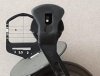
8. Remove the trigger safety (picture 07, purple arrow)
9. Place the RPG-75 on the right shoulder, place the finger behind the trigger (Picture 07, green arrow).
10. Aim at the target and move the trigger forward (direction green arrow), untill the firing pin (picture 08) until it flips over like a mousetrap, igniting the firing cap of the motor.
The firing cap ignites the black powder charge in top of the motor, which ignites the main powder charge. The hot powder gasses move in two directions; to the back through the grid and out of the venturi, and forward through the hole in the yoke shaped bushing, filling the space between the projectile and the top flange of the motor with hot gasses until the pressure has risen so high that the two dowels on top of the two screws fail and the projectile is thrown away with force to the target.
It is ill adviced to attack a modern MBT up frontal with the RPG-75, as the armour of most modern tanks is the equivalent of between 750mm to 1000 mm steel. It is better to wait until the tank has passed and shoot in the much weaker armoured motor compartiment or ammo storage.
The weapon is however very suitable to attack APC’s and lightly armoured vehicles.
Data RPG-75:
Calibre : 68 mm
Folded length : 633 mm
Extended length : 890 mm
Armour penetration : >330 mm
Weight complete RPG-75 : 3,2 kg
Weight projectile : 0,8 kg
Weight explosive charge : 0,32 kg
Vo. : 189 mtr/ sec
Self detruction : between 3 en 6 seconden
Temperature range : from -40 to +50 graden celcius
Effective range : 200 mtrs with moving target, 300 mtrs with static target.
Regards, DJH
The RPG-75 (pict 1 to 4) consists of an aluminium tube in which a recoiless cartridge (pict.05) is placed. The cartridge is fixated in the pipe by means of a bayonet mount which is placed in the backside of the aluminium pipe. The counterparts of the bayonet fitting are placed on both the forward part of the aluminium nosecap of the pressure chamber and the outside of the aft part of the venturi. To make the RPG-75 ready for use the aluminium pipe is taken in one hand, and the other hand grips the flange of the venturi. The venturi is rotated 30 degrees counterclockwise to release it form the bayonet mount, the cartridge is pulled backward and telescoped out, and the venturi is rotated 30 degrees clockwase to lock the forward bayonet mount. By locking the bayonet mount in the forward position, the firing cap of the motor is placed in line of the firing pin. (pict 08).
The cartridge (pict. 05) consists of a shaped charge with a PIBD (Point Ignited Base Detonated ) fuze , also called a spit back fuze. The steel housing of the nose part of the fuze forms the stand off; the optimum distance between the cone and the target to archieve maximum target penetration. The inside of the nose part of the fuze houses a impact fuze with a zig-zag delay safety mechanism with an impact detonator in the forward part and a flame sensitive detonator at the base. Upon impact the impact detonator is ignited, the flame travels down into the flame sensitive detonator and the flame of this detonator travels downward through the ccone into the base part of the fuze.
This base part of the fuze is kept out of line with the booster charge penthrite (pink) when safe. Upon firing, inertia releases the flame sensitive lower detonator, which is moved forward into the armed position by a spring.
Behind this flame sensitive lower detonator, a hollow screw with a pyrotechnic delay fuze is screwed into the base of the fuze; if the target is missed, it will ignite the flame sensitive lower detonator in between 3 to 6 seconds. This is the self destruct mechanism.
A wave shaper (white) is placed in the explosive charge; this forces the detonation wave is a more favorable shape before reaching the cone, enhancing the armour penetration between 10 to 15%.
The warhead is connected to the motor by means of yoke shaped steel bushing with a hole in the center. A radial placed screw is screwed through both yokes, both screws having a dowel at the inward facing end. Both these dowels are placed in opposite radial holes drilled in the outside of the lower fuze housing, fixating the warhead to the motor.
The yoke shaped bushing is bolted into the aluminium top flange of the motor, which also houses the firing cap to ignite the propelling charge . A hard and tough steel pipe is screwed into the base of the top flange, forming the combustion chamber. The venturi is screwed into the base of the steel pipe. Above the venturi , a cone shaped grid is placed to enshure no half- or unburned powdersticks will leave the combusion chamber.
The powdercharge consists of a bundle of 3,5 mm diameter and 180mm long perforated sticks with a bag of black powder sewed to the top top enshure a even and simultanious ignition of the powder charge. This bag of black powder is placed in way of the firing cap.
Functioning:
1. Remove the protective rubber front cap.
2. Rotate the flange of the venturi 30 degrees anti-clockwise so the bayonet mount comes loose.
3. Pull the cartridge backward untill it cannot move further.
4. Rotate the bayonet mount 30 degrees clockwise to fixate the cartridge in the firing position.
5. Remove the transport safety (picture 0 , red arrow)
6. Flip up the forward sight by pushing the latch below the front cover.
7. Pull the aft sight away from under the rubber protective band and flip it upward.
8. Remove the trigger safety (picture 07, purple arrow)
9. Place the RPG-75 on the right shoulder, place the finger behind the trigger (Picture 07, green arrow).
10. Aim at the target and move the trigger forward (direction green arrow), untill the firing pin (picture 08) until it flips over like a mousetrap, igniting the firing cap of the motor.
The firing cap ignites the black powder charge in top of the motor, which ignites the main powder charge. The hot powder gasses move in two directions; to the back through the grid and out of the venturi, and forward through the hole in the yoke shaped bushing, filling the space between the projectile and the top flange of the motor with hot gasses until the pressure has risen so high that the two dowels on top of the two screws fail and the projectile is thrown away with force to the target.
It is ill adviced to attack a modern MBT up frontal with the RPG-75, as the armour of most modern tanks is the equivalent of between 750mm to 1000 mm steel. It is better to wait until the tank has passed and shoot in the much weaker armoured motor compartiment or ammo storage.
The weapon is however very suitable to attack APC’s and lightly armoured vehicles.
Data RPG-75:
Calibre : 68 mm
Folded length : 633 mm
Extended length : 890 mm
Armour penetration : >330 mm
Weight complete RPG-75 : 3,2 kg
Weight projectile : 0,8 kg
Weight explosive charge : 0,32 kg
Vo. : 189 mtr/ sec
Self detruction : between 3 en 6 seconden
Temperature range : from -40 to +50 graden celcius
Effective range : 200 mtrs with moving target, 300 mtrs with static target.
Regards, DJH
Attachments
-
 01 - RPG-75 backside.jpg280.2 KB · Views: 58
 -
 02 - RPG-75 cutaway model.jpg307.7 KB · Views: 73
 -
 03 - RPG-75 extended backside.jpg293.3 KB · Views: 57
 -
 04 - RPG-75 extended backside cutaway.jpg257.2 KB · Views: 61
 -
 05 - RPG-75 cartidge.jpg262.8 KB · Views: 65
 -
 06 - shaped charge.jpg315 KB · Views: 63
 -
 07 - trigger mechanism 1.jpg281.4 KB · Views: 52
 -
 08 - trigger mechanism 2.jpg280.2 KB · Views: 50
 -
 09 - sighting system.jpg114.2 KB · Views: 48
Last edited:
")
