Manufacturing a cutaway model of a WW2 Brittish 20x10 Hispano Suiza (HS404) High Explosive Incendiary (HEI) shell, fuzed with the DA (Direct Action) 254 fuze. A full posting about 20x110 HS cartridges will follow.
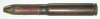
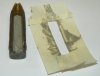
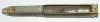
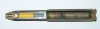
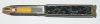
01- The cartridge before being cut
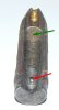
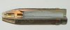
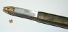
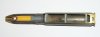
02- The projectile after cutting. Because there are no moving parts in the fuze and the cut of the fuze shows the same in every angle cut around the circumference, the fuze parts are assembled and screwed tight. The fuze assembly is screwed tight on the projectile body. Place the projectile in a vice and cut out 90 degrees (1/4), either 120 degrees (1/3). Make shure the cutting line is 1 mm cut before the centerline, so about 0,8mm has to be removed to straighten the cutaway surfaces of the projectile. Drill a small (2 or 3 mm dia.) hole on the inside of the body i.w.o the driving band, approximately 2,5mm deep, however make shure you do not drill through the body. Place a small pin (red arrow) of the correct diameter in the hole, however make shure it stays at least 1mm below the centerline of the projectile so it will not stick through the polyester filling later on. This pin fixates the cast in polyester filling from rotating or moving. With this projectile two fuzes can be used; the DA 254 with a short detonator above which a brass disc with a small hole is placed, either the DA 253 with a long detonator (see pict 14) that protrudes in the explosive charge above which a brass disc with a bigger tapered hole is placed. Therefore , with fuze 254 one can use a small 1 mm thick cartboard disc (green arrow), greased with bearinggrease either petrolium jelly. If fuze DA 253 is used, a casting template is to be machined from nylon. It has to be lightly greased before being used for casting purposes.
03- Place masking tape around the casting position.
04- Place the polyester putty in the explosive filler space with a flat screwdriver (No philips head crewdriver). If fuze DA 253 is used it is better to first fill the forward part of the projectile with polyester and than insert the nylon template. By gently hamering the base of the projectile with a small hammer, the polyester will settle. Clean the screwdriver carefully with an old piece of cloth.
05- Remove the masking tape while the polyester is still fully liquid. Hardening takes at least one hour.
06- Remove the overflow of hardened polyester from the center. Each rasp has a side with and without side teeth. Use this side together with the normal flat side of the rasp to carefully rasp a longitudal slot in the polyester untill the surface of the polyester is paralell with the steel of the cut surfaces. As soon as one feels the rasp touching brass or steel, check if you are not rasping away too much from top or base, either rasp below the centerline.
07- Remove 0,5 mm by rasping, meanwhile enshuring the cut surfaces are straight, the 90 or 120 degrees angle is maintained. Also check if the cut surface is 90 degrees to a flat surface with a carpenters hook with the projectile in standing position. Rasp agian, but with a very light pressure, so longitudal rasping grooves are removed. Use pressurized air (can also be obtained as reversable air in a computer shop) to blow the cutaway model clean. Small holes in the polyester will now become visable.
08- Fill the small holes again with polyester
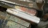
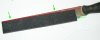
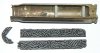
09- Cut the shellcase. Place the projectile on the shellcase to determine the angle to be cut out.
10- Fold P80 sandpaper (from a roll) over the rasp as shown in the picture on the side of the rasp where there are no side teeth. By folding the sandpaper slightly inward on the top (red lines and anle ) one prevents the sandpaper from damaging the other cutaway surface. The lower portion on the rasp is kept paralell with the outer line of the rasp (green lines and arrows).
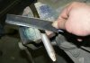
11- Pull the sandpaper tight over the rasp and pinch it between thumb and indexfinger. Polish the cutaway surface of the projectile (with fuze).
12- Again clean the cutaway model with presurized air and refill any small holes left with polyester putty again. Machine a dummy detonator from red copper . When the polyester is dry, ploish for a last time.
13- Paint in the tetrylcharge (yellow), the thermite charge (gray) and the leadazide (white) in the detonator with modeller’s paint. Glue the felt washer on top of the Tetryl charge and replace the fuze. Wear plastic gloves (from gasoline station) to enshure one does not handle the cutaway surfaces of projectile and fuze with sweated fingers as this will cause corrosion. Paint (aerosol) the cutaway with transparant varnish.
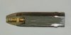
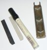
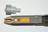
14- Here the projectile with the DA 253 fuze and the machined white nylon casting template.
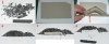
15- Place three cut out cartboard discs (in this case ø22mm) in the shellcase. The cartboard must be 3 mm thick.
16- Draw two lines from the cutaway surface of the shellcase to the center (light blue lines to purple +) of the disc. From this line, deduct the thickness of the cartboard (3mm) and the fake powder (2 mm dia ground spagetti) =5mm (dark blue lines) Cut out over the purple lines. Glue the lower and middle cartboard template in the shellcase, colour the upper one black. The width of the longitudal template on which the powder is placed is derived from the length of the chord minus the catrboard thickness (red and green square)
17- Determine the length of the upper template (filled till just under the neck of the shellcase) and cut to length. Paint the side to which the powder is glued black.
18- Scatter some fake powder over a flat surface (1). Place a piece of cartboard over the powder and force it into a one thich layer by gently rotating the piece of cartbaord (2). Place a ruler (3) along the straight edge of the cartbaord and gently move backward zig-zagging. This will settle the powder and form a straight edge (4) along the fake powder. Put a thick layer of glue (appr 0,4mm thick) on the black painted side of the upper template and place the edge facing the centerline of the cutaway model on the edge of the fake powder (5). Remove fake powder sticking out the cartboard template and replace it with single granulars that fit the tempalte (6).
19- Paint (aerosol) the shellcase cutaway with transparant varnish and let the paint dry.
20- Glue the powder templates in the shellcase to the circular templates and glue the projectile to the sellcase.
Regards, DJH
01- The cartridge before being cut
02- The projectile after cutting. Because there are no moving parts in the fuze and the cut of the fuze shows the same in every angle cut around the circumference, the fuze parts are assembled and screwed tight. The fuze assembly is screwed tight on the projectile body. Place the projectile in a vice and cut out 90 degrees (1/4), either 120 degrees (1/3). Make shure the cutting line is 1 mm cut before the centerline, so about 0,8mm has to be removed to straighten the cutaway surfaces of the projectile. Drill a small (2 or 3 mm dia.) hole on the inside of the body i.w.o the driving band, approximately 2,5mm deep, however make shure you do not drill through the body. Place a small pin (red arrow) of the correct diameter in the hole, however make shure it stays at least 1mm below the centerline of the projectile so it will not stick through the polyester filling later on. This pin fixates the cast in polyester filling from rotating or moving. With this projectile two fuzes can be used; the DA 254 with a short detonator above which a brass disc with a small hole is placed, either the DA 253 with a long detonator (see pict 14) that protrudes in the explosive charge above which a brass disc with a bigger tapered hole is placed. Therefore , with fuze 254 one can use a small 1 mm thick cartboard disc (green arrow), greased with bearinggrease either petrolium jelly. If fuze DA 253 is used, a casting template is to be machined from nylon. It has to be lightly greased before being used for casting purposes.
03- Place masking tape around the casting position.
04- Place the polyester putty in the explosive filler space with a flat screwdriver (No philips head crewdriver). If fuze DA 253 is used it is better to first fill the forward part of the projectile with polyester and than insert the nylon template. By gently hamering the base of the projectile with a small hammer, the polyester will settle. Clean the screwdriver carefully with an old piece of cloth.
05- Remove the masking tape while the polyester is still fully liquid. Hardening takes at least one hour.
06- Remove the overflow of hardened polyester from the center. Each rasp has a side with and without side teeth. Use this side together with the normal flat side of the rasp to carefully rasp a longitudal slot in the polyester untill the surface of the polyester is paralell with the steel of the cut surfaces. As soon as one feels the rasp touching brass or steel, check if you are not rasping away too much from top or base, either rasp below the centerline.
07- Remove 0,5 mm by rasping, meanwhile enshuring the cut surfaces are straight, the 90 or 120 degrees angle is maintained. Also check if the cut surface is 90 degrees to a flat surface with a carpenters hook with the projectile in standing position. Rasp agian, but with a very light pressure, so longitudal rasping grooves are removed. Use pressurized air (can also be obtained as reversable air in a computer shop) to blow the cutaway model clean. Small holes in the polyester will now become visable.
08- Fill the small holes again with polyester
09- Cut the shellcase. Place the projectile on the shellcase to determine the angle to be cut out.
10- Fold P80 sandpaper (from a roll) over the rasp as shown in the picture on the side of the rasp where there are no side teeth. By folding the sandpaper slightly inward on the top (red lines and anle ) one prevents the sandpaper from damaging the other cutaway surface. The lower portion on the rasp is kept paralell with the outer line of the rasp (green lines and arrows).
11- Pull the sandpaper tight over the rasp and pinch it between thumb and indexfinger. Polish the cutaway surface of the projectile (with fuze).
12- Again clean the cutaway model with presurized air and refill any small holes left with polyester putty again. Machine a dummy detonator from red copper . When the polyester is dry, ploish for a last time.
13- Paint in the tetrylcharge (yellow), the thermite charge (gray) and the leadazide (white) in the detonator with modeller’s paint. Glue the felt washer on top of the Tetryl charge and replace the fuze. Wear plastic gloves (from gasoline station) to enshure one does not handle the cutaway surfaces of projectile and fuze with sweated fingers as this will cause corrosion. Paint (aerosol) the cutaway with transparant varnish.
14- Here the projectile with the DA 253 fuze and the machined white nylon casting template.
15- Place three cut out cartboard discs (in this case ø22mm) in the shellcase. The cartboard must be 3 mm thick.
16- Draw two lines from the cutaway surface of the shellcase to the center (light blue lines to purple +) of the disc. From this line, deduct the thickness of the cartboard (3mm) and the fake powder (2 mm dia ground spagetti) =5mm (dark blue lines) Cut out over the purple lines. Glue the lower and middle cartboard template in the shellcase, colour the upper one black. The width of the longitudal template on which the powder is placed is derived from the length of the chord minus the catrboard thickness (red and green square)
17- Determine the length of the upper template (filled till just under the neck of the shellcase) and cut to length. Paint the side to which the powder is glued black.
18- Scatter some fake powder over a flat surface (1). Place a piece of cartboard over the powder and force it into a one thich layer by gently rotating the piece of cartbaord (2). Place a ruler (3) along the straight edge of the cartbaord and gently move backward zig-zagging. This will settle the powder and form a straight edge (4) along the fake powder. Put a thick layer of glue (appr 0,4mm thick) on the black painted side of the upper template and place the edge facing the centerline of the cutaway model on the edge of the fake powder (5). Remove fake powder sticking out the cartboard template and replace it with single granulars that fit the tempalte (6).
19- Paint (aerosol) the shellcase cutaway with transparant varnish and let the paint dry.
20- Glue the powder templates in the shellcase to the circular templates and glue the projectile to the sellcase.
Regards, DJH
Attachments
-
 01 - 20x110 HS HEI before cutting.JPG63.6 KB · Views: 59
 -
 02 - 20x110 HS HEI after cutting head, placing pin and placing greased disc.JPG72.5 KB · Views: 64
 -
 03 - 20x110 HS HEI masking tape before pouring polyester putty.JPG46.4 KB · Views: 60
 -
 04 - 20x110 HS HEI polyester poured.JPG40.3 KB · Views: 55
 -
 05 - 20x110 HS HEI removal of masking tape.JPG86.2 KB · Views: 58
 -
 06 - 20x110 HS HEI removal of exess polyester putty.JPG71.2 KB · Views: 57
 -
 07 - 20x110 HS HEI after rasping straight.JPG53.4 KB · Views: 60
 -
 08 - 20x110 HS HEI after second rounsd of polyester putty (filling holes and cracks).JPG45.6 KB · Views: 58
 -
 09 - 20x110 HS HEI shellcase cut and straightened.JPG75.4 KB · Views: 52
 -
 10 - 20x110 HS HEI sandpaper over rasp.JPG67.1 KB · Views: 52
 -
 11 - 20x110 HS HEI correct way to keep sandpaper over rasp..JPG87 KB · Views: 57
 -
 12 - 20x110 HS HEI Filling small holes and machining dummy detonator.JPG82.2 KB · Views: 55
 -
 13 - 20x110 HS HEI painting in explosive filler and applying varnish layer.JPG91 KB · Views: 55
 -
 16 - 20x110 HS HEI cartboard templates for shellcase cut.JPG96 KB · Views: 52
 -
 17 - 20x110 HS HEI longitudal templates in shellcase.JPG125.6 KB · Views: 56
 -
 18- 20x110 HS HEI gluing on fake powder.JPG175.5 KB · Views: 54
 -
 19 - 20x110 HS HEI templates filled with fake powder.JPG128.7 KB · Views: 61
 -
 20 - 20x110 HS HEI cutaway model complete..JPG93.8 KB · Views: 65
 -
 15 - 20x10 HS HEI cartboard discs in shellcase.JPG99.3 KB · Views: 59
 -
 14 - same shell with DA 253 fuze and nylon casting negative.jpg66.8 KB · Views: 66


")