Daniels and Gardiner percussion grenades have appeared briefly in previous threads, for example D&G Grenades (bocn.co.uk). Herewith a description of a representative D&G grenade, the D&G No.4, and a very brief summary of the abortive Daniels and Gardiner grenade story.
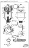
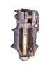
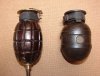
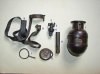
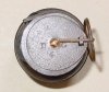
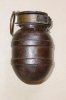
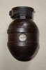
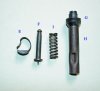
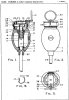
The images show various aspects of a furnished D&G No.4 grenade, and then stripped down and labelled to correspond with the description of operation. The cocked striker is shown removed from its housing. The grenade lacks its base plug, into which a rifle rod could be screwed.
To use, the safety pin and ring pull (L) was withdrawn, freeing the weight (A) at the outer end of a 28” (70cm) tape (B) and the grenade thrown or launched from a rifle. The tape unwound until the safety peg (C) at the inner end was free to be ejected by the spiral spring (D). The grenade was now fully armed, the spring-loaded striker (F) being held in place purely by the compression force of the striker spring (I) acting on a blade, trapped between the top flange of the striker (F) and the collar of the fuze chamber central plug (G). The blade was curved with an asymmetric weight (E) at the end - the shock of the grenade landing caused the weight to act to dislodge the blade, releasing the striker to fire down under the force of its spring to the detonator in its sleeve (H), and set off the grenade.
The D&G series ran to eight variants, or marks, from early 1916 to mid-1918, and the operating principle – eccentric weight and tape-and-peg delay and safety device - was common to all. Detailed improvements in safety and reliability were claimed by the inventors with increasing mark, but the Munitions Design Committee responsible for testing the device begged to differ.
British Patents No.124837 of May 1916 and No.129042 of October 1917 effectively describe the D&G No.5 and D&G No.8, respectively. The internals of the No.4 are identical schematically to the drawing of Patent No.124837. According to a publicity document produced by the inventors, some 6,730 grenades had been fired in UK trials up to the 1st June 1917. However, senior staff on the Design Committee had noted in October 1916, “no form of percussion grenade in which the striker is retained by a compressed spring should be considered”, as the chances of a premature were unacceptable, while a blind would be particularly dangerous to dispose of. Irrespective of the official view of such a design, Daniels and Gardiner persisted with their development, even lobbying the then Minister for Munitions, Mr Winston Churchill, to promote their cause.
By December 1917, Sir Douglas Haig had confirmed the intent for the Army in France to trial 1,000 D&G grenades* (and 1,000 of the equally dubious Chamier percussion grenades), and orders for the D&G were placed with J Griffin & Sons Ltd, London. This firm was, however, unable to give an immediate quotation for supply as they explained that “the grenade, as at present designed, does not function satisfactorily and therefore, further experimental work is necessary”. There followed four months of delay and excuses before the first completed items were sent for filling, but then the Munitions Inventions Department found the design “not efficient” and ordered the grenades to be returned to the manufacturer for alteration. 108 were modified for improved safety and sent back to MID, where the grenade duly failed the resumed safety and sensitivity tests.
By 22 June 1918 the French trials were cancelled and all further evaluation by MID had ceased. The Daniels & Gardiner grenade did not progress further, in part because of more promising developments with the large percussion egg grenades being considered for the 2” discharger cup - the CSOF, Bellamy, Cole, Midgeley, and Vickery.
*Being the final mark, the No.8 variant.
Tom.
Attachments
-
 D&G MkIV_11.jpg85.9 KB · Views: 34
 -
 D&G MkIV_10.jpg102.9 KB · Views: 37
 -
 D&G MkIV_9.jpg293.5 KB · Views: 38
 -
 D&G MkIV_3.JPG230.1 KB · Views: 32
 -
 D&G MkIV_2.jpg72.9 KB · Views: 42
 -
 D&G MkIV_1.jpg77.4 KB · Views: 31
 -
 D&G MkIV_13.jpg212.8 KB · Views: 33
 -
 Pat. No.124837.jpg205 KB · Views: 35
 -
 D&G MkIV_14.jpg291.6 KB · Views: 38
Last edited: