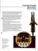
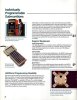
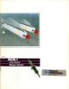
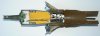
Cutaway model of a ISCB-1 clustermine. The mine is released from a Mk-7 dispenser -the same as used for the Mk-20 Rockeye-, however the tail of the Mk-7 dispenser is adepted in taking the electronic circuits for the delay distribution of the mines. The Mk-7 dispenser contains 160 ISCB-1s, as well as 65 dummy mines. The maximum delay (electronic) is 72 hours (3 days). The dummy mines are included to give the enemy the feeling the area is still unsafe as one does not know at what time the mines have been deployed and which are real and which are dummy,s.
Before the dispenser is hung on the plane,s bomb rack, a pre-set time program is entered, determining the detonation time of each single ISCB-1 mine. This ensures the area is denied to the enemy, while time windows can be built in during which the mines are switched off, enabling friendly troops to pass through the minefield without danger.
There is no movement sensor or anti tampering device on the ISCB-1; activation is done purely by the electronic timer pre-programmed on the airfield. This raises the question of definition of the submunition as a mine, an explosive charge with a preprogrammed timer might be more accurate.
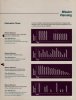
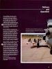
Maximum effect of this weapon can be archieved when used against artillery positions, airfields (runways , either to deny it's repair or among parked aircraft), bridges, supply points, choke points, Sam or AAA positions, etc. On page 08 of the factory brochure examples can be found of preprogramed time scemes. By (for instance) setting 25% of the ISCB-1,s at exploding nearly direct after impact, personel will flee from it's positions. By spreading detonations of the other 75% of the ISCB-1,s over the rest of the 72 hours one keeps the enemy personel away from it's positions.
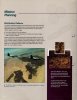
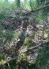
The only known time the ISCB-1 has been deployed in quite large numbers was in the first gulf war when it was deployed in the western H2/H3 sector in Iraq in an attempt to hamper Scud launchers from being deployed. The main advantage of the ISCB-1 is that it can easily be deployed in deep in enemy terratory, even in places that are difficult to acces.
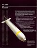
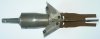
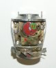
The mine is constructed of a pressed steel body on which a pressed steel nose cone is crimped in place. In the mine body a nylon housing is placed with hardened steel balls cast into the lower part. In the upper part of the housing the disc with the electronic timer device and the battery are placed, cast in pur foam to make the parts impact resistant. On top of the nylon housing a steel cap is glued in place which acts as an extra protective cap upon impact. An explosive charge , existing of Comp. B (yellow) is placed in the lower part of the mine body. In the lower part of the bomb body a connecting ring is crimped in place over which a clamping ring is placed which keeps the mine body, the fuze housing and the tail together. The retardation fins exist of three bend stainless steel plates covered with canvas in a camouflage pattern. The three retardation fins are an integraf part of the tail.
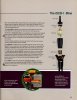
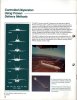
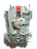
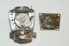
I do not know the type designation of the fuze. A turbine wheel (1) is mounted to the base of the fuze. It starts to rotate fast when released in the airstream after ejection from the dispener. In the hub (2) of the turbine wheel two plates (3) are mounted on two opposite axial shafts. Two blade springs keep these plates in the inward position. On top of these two plates a spring (5) mounted locking pin (4) is placed. In it's upper position this locking pin fixates the rotor (6) against rotating from safe to armed. When the turbine wheel starts rotating fast, the plates (3) are thrown outward, enabeling the locking pin (4) to move down and release the rotor. By rotating the rotor (6) 90 degrees, the electrically ignited detonator (7) is placed in line with the booster (8), arming the mine. The rotor is rotated by a spring driven reduction gerabox (9), which starts to rotate the rotor as soon as the locking pin (4) is retracted. A curved tooth gear (10) is screwed to the last part of the path of the rotor. On top of the hub a small gear wheel is mounted that grips into this curved tooth gear and enshures the rotor is rotated to it's full end.
A small wheel (11) is mounted to the outside of the reduction gear, painted red with a small green section. A small hole is drilled in the protective housing i.w.o. the wheel. Looking through this hole one can see either a green dot (safe), either red (armed)
After a certian preprogrammed time the timer will send a signal to the electric detonator (7), exploding the mine.
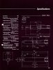
Details :
Weight : 0,52 Kg
Explosives weight : 0,18 kg Comp. B
Length : 320 mm
Body diameter : 53 mm
Diameter with retardation fins extended : 100 mm
I have added a factory brochure of the ISCB-1
Regards, DJH
Before the dispenser is hung on the plane,s bomb rack, a pre-set time program is entered, determining the detonation time of each single ISCB-1 mine. This ensures the area is denied to the enemy, while time windows can be built in during which the mines are switched off, enabling friendly troops to pass through the minefield without danger.
There is no movement sensor or anti tampering device on the ISCB-1; activation is done purely by the electronic timer pre-programmed on the airfield. This raises the question of definition of the submunition as a mine, an explosive charge with a preprogrammed timer might be more accurate.
Maximum effect of this weapon can be archieved when used against artillery positions, airfields (runways , either to deny it's repair or among parked aircraft), bridges, supply points, choke points, Sam or AAA positions, etc. On page 08 of the factory brochure examples can be found of preprogramed time scemes. By (for instance) setting 25% of the ISCB-1,s at exploding nearly direct after impact, personel will flee from it's positions. By spreading detonations of the other 75% of the ISCB-1,s over the rest of the 72 hours one keeps the enemy personel away from it's positions.
The only known time the ISCB-1 has been deployed in quite large numbers was in the first gulf war when it was deployed in the western H2/H3 sector in Iraq in an attempt to hamper Scud launchers from being deployed. The main advantage of the ISCB-1 is that it can easily be deployed in deep in enemy terratory, even in places that are difficult to acces.
The mine is constructed of a pressed steel body on which a pressed steel nose cone is crimped in place. In the mine body a nylon housing is placed with hardened steel balls cast into the lower part. In the upper part of the housing the disc with the electronic timer device and the battery are placed, cast in pur foam to make the parts impact resistant. On top of the nylon housing a steel cap is glued in place which acts as an extra protective cap upon impact. An explosive charge , existing of Comp. B (yellow) is placed in the lower part of the mine body. In the lower part of the bomb body a connecting ring is crimped in place over which a clamping ring is placed which keeps the mine body, the fuze housing and the tail together. The retardation fins exist of three bend stainless steel plates covered with canvas in a camouflage pattern. The three retardation fins are an integraf part of the tail.
I do not know the type designation of the fuze. A turbine wheel (1) is mounted to the base of the fuze. It starts to rotate fast when released in the airstream after ejection from the dispener. In the hub (2) of the turbine wheel two plates (3) are mounted on two opposite axial shafts. Two blade springs keep these plates in the inward position. On top of these two plates a spring (5) mounted locking pin (4) is placed. In it's upper position this locking pin fixates the rotor (6) against rotating from safe to armed. When the turbine wheel starts rotating fast, the plates (3) are thrown outward, enabeling the locking pin (4) to move down and release the rotor. By rotating the rotor (6) 90 degrees, the electrically ignited detonator (7) is placed in line with the booster (8), arming the mine. The rotor is rotated by a spring driven reduction gerabox (9), which starts to rotate the rotor as soon as the locking pin (4) is retracted. A curved tooth gear (10) is screwed to the last part of the path of the rotor. On top of the hub a small gear wheel is mounted that grips into this curved tooth gear and enshures the rotor is rotated to it's full end.
A small wheel (11) is mounted to the outside of the reduction gear, painted red with a small green section. A small hole is drilled in the protective housing i.w.o. the wheel. Looking through this hole one can see either a green dot (safe), either red (armed)
After a certian preprogrammed time the timer will send a signal to the electric detonator (7), exploding the mine.
Details :
Weight : 0,52 Kg
Explosives weight : 0,18 kg Comp. B
Length : 320 mm
Body diameter : 53 mm
Diameter with retardation fins extended : 100 mm
I have added a factory brochure of the ISCB-1
Regards, DJH
Attachments
-
 ISCB-1 view backside.jpg94.5 KB · Views: 97
 -
 ISCB-1 cutaway fuze complete.JPG55.1 KB · Views: 100
 -
 ISCB-1 backside fuze with reduction gear.JPG41.6 KB · Views: 87
 -
 ISCB-1 backside fuze arming disc, reduction gear removed.JPG70.3 KB · Views: 75
 -
 ISCB-1 fragmentation sleeve.JPG34.6 KB · Views: 87
 -
 ISCB-1 as found in nature.jpg98.5 KB · Views: 100
 -
 ISCB-1 view cutaway side.jpg95.5 KB · Views: 115
Last edited by a moderator: