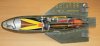
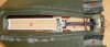
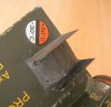
Cutaway model of an ENTAC (ENgine Teleguide Anti Char), which translates as “Anti Tank Guided Missile”. The missile was designed by DTAT (Direction Technique des Armements Terrestres/ Technicaldepartment of land warfare), and 140.000 pcs. were produced by Aerospatiale.
The ENTAC was the follow up of the SS-10 Anti tank missile -designed in 1948-, which was a derict derivate of the German WW2 X-7 missile.
The missile is of the MCLOS (Manual Command Line Of Sight) type, a first generation guidance control missile. It is fired from a simple box-like launcher, it is wire guided by means of two wires, and is optically tracked and manually guided by the operator using a small joystick and a periscope-type telescopic sight.. A single operator can control a vehicle-based firing post with up to 10 missiles. The operator must track the missile and the target simultaneously and guide the missile to the target, what takes training, skill and lots of concentration.
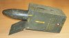
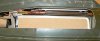
The missile has a two stage solid propellant motor, existing of a starting pulse motor and a sustainer motor.
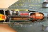
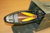
The starting impulse motor fuel exists of five tubular powder sticks of light pressing whom burn up instantaniously. The powder stick of the sustainer motor is of hard pressing and burns up slowly with a lower pressure than the starting impulse motor. The powder stick of the sustainer motor is packed in a heat resistant rubber cover that keeps the aluminium motor housing relatively cool.
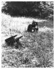
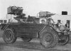
The ENTAC is meant for use against tanks, armoured cars, unarmoured vehicles, bunkers and field fortifications. It was used from an array of vehicles, from jeeps to armoured vehicles to small hand towed karts.
The USA extensively tested the ENTAC as project T-581 at the redstone arsenal, Alabama and the Aberdeen proving grounds in Maryland. It was taken into service as the MGM-32, however the US forces used a different shaped (Pointed with flat nose) warhead. It was officaly taken into service in 1963, to be replaced only six years later by the BGM-71 TOW missile.
Upon firing, the following sequence of events happen:
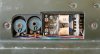
-The battery (A) is activated by a liquid or gas being injected into the battery. This is kept in a small bottle in the back of the crate. A ball (B) in the back of the battery acts as a non return valve. The missile is now electrically activated.
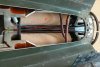
-The starting pulse motor ignites (C), giving the misile it’s operational speed and launches it from the crate.
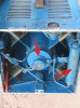
-A wire is wound around the wheel (D)of the gyroscope and connected to the launching crate. (this wire leaves the body of the missile at the blue arrow). Upon launch, the wire makes the gyroscope spin, rotating the missile clockwise for 45 degrees from a x wing posiyion into a + wing position after leaving the crate and flying to the target**
-The sustainer motor (E) is started at the same moment as the starting pulse motor. This sustains the initial speed created by the starting pulse motor. A channel (F) drilled in the baseplate of the sustainer motor leads to a filter (G) and a small needle tube (H) that ends up in a red copper pipe (J). This pipe ends up in the fuze (K) where it pneumatically pushes the safety out of line, arming the fuze. The time needed to fill the red copper pipe with enough pressure to push away the safety enshures the missile is not armed in the initial 400 meters of flight.
- The missile is now fully armed, the electric detonator is aligned behind the hollow charge. In the nose of the missile an electric impact contact switch (L) is placed. Upon impact this contact is closed, igniting the detonator, exploding the shaped charge.
The command signals to the missile are transmitted through two steel wires that unroll from two spools (M) placed in the missile body. Two sets of steering switches (N) and spools (O) are placed in the missile body – each connected to one spool wire-, one set for the left /right movement, one set for up/down movement. These switches actuate sets of magnets that pull down the spoilers (P) to one of either sides of the wing, so influencing the airflow over the wings and steering the missile.
The Entac has been used by the following countries:
Australia 1964-1982, France 1957-1970, India 1968-?, Iran 1966-1988, Israel 1963-?, Lebanon 1967-?, South Africa 1969-1984, United States 1963-1969.
A very interesting site depicting the ENTAC missile can be found here:
http://servir-et-defendre.com/viewtopic.php?f=109&t=1475
Year of service entry : 1957
Weight : 12,2 kg.
Length : 820 mm.
Diameter : 152 mm.
Wingspan : 375 mm.
Operational Range : 400 mtrs minimal up to 2000 mtrs maximum.
Speed : 100 mtrs/sec , 360 km/hr.
Warhead : a 4 kg hollow charge able to penetrate 650 mm (25 inches)of RHA.
** On many internet sources, it is mentioned that the missile is roll stabilized. However, studying the gyroscope it apperared to me that is was made in such a way that the missile would rotate clockwise 45 degrees, than locking the missile in it’s rolling movement by a two switches connected to the gyroscope’s cage. When rolling counterclockwise, the clockwise swich is activated , rolling the missile slightly clockwise, and visa verca enshuring the missile takes a + wing position when flying to the target.
The ENTAC was the follow up of the SS-10 Anti tank missile -designed in 1948-, which was a derict derivate of the German WW2 X-7 missile.
The missile is of the MCLOS (Manual Command Line Of Sight) type, a first generation guidance control missile. It is fired from a simple box-like launcher, it is wire guided by means of two wires, and is optically tracked and manually guided by the operator using a small joystick and a periscope-type telescopic sight.. A single operator can control a vehicle-based firing post with up to 10 missiles. The operator must track the missile and the target simultaneously and guide the missile to the target, what takes training, skill and lots of concentration.
The missile has a two stage solid propellant motor, existing of a starting pulse motor and a sustainer motor.
The starting impulse motor fuel exists of five tubular powder sticks of light pressing whom burn up instantaniously. The powder stick of the sustainer motor is of hard pressing and burns up slowly with a lower pressure than the starting impulse motor. The powder stick of the sustainer motor is packed in a heat resistant rubber cover that keeps the aluminium motor housing relatively cool.
The ENTAC is meant for use against tanks, armoured cars, unarmoured vehicles, bunkers and field fortifications. It was used from an array of vehicles, from jeeps to armoured vehicles to small hand towed karts.
The USA extensively tested the ENTAC as project T-581 at the redstone arsenal, Alabama and the Aberdeen proving grounds in Maryland. It was taken into service as the MGM-32, however the US forces used a different shaped (Pointed with flat nose) warhead. It was officaly taken into service in 1963, to be replaced only six years later by the BGM-71 TOW missile.
Upon firing, the following sequence of events happen:
-The battery (A) is activated by a liquid or gas being injected into the battery. This is kept in a small bottle in the back of the crate. A ball (B) in the back of the battery acts as a non return valve. The missile is now electrically activated.
-The starting pulse motor ignites (C), giving the misile it’s operational speed and launches it from the crate.
-A wire is wound around the wheel (D)of the gyroscope and connected to the launching crate. (this wire leaves the body of the missile at the blue arrow). Upon launch, the wire makes the gyroscope spin, rotating the missile clockwise for 45 degrees from a x wing posiyion into a + wing position after leaving the crate and flying to the target**
-The sustainer motor (E) is started at the same moment as the starting pulse motor. This sustains the initial speed created by the starting pulse motor. A channel (F) drilled in the baseplate of the sustainer motor leads to a filter (G) and a small needle tube (H) that ends up in a red copper pipe (J). This pipe ends up in the fuze (K) where it pneumatically pushes the safety out of line, arming the fuze. The time needed to fill the red copper pipe with enough pressure to push away the safety enshures the missile is not armed in the initial 400 meters of flight.
- The missile is now fully armed, the electric detonator is aligned behind the hollow charge. In the nose of the missile an electric impact contact switch (L) is placed. Upon impact this contact is closed, igniting the detonator, exploding the shaped charge.
The command signals to the missile are transmitted through two steel wires that unroll from two spools (M) placed in the missile body. Two sets of steering switches (N) and spools (O) are placed in the missile body – each connected to one spool wire-, one set for the left /right movement, one set for up/down movement. These switches actuate sets of magnets that pull down the spoilers (P) to one of either sides of the wing, so influencing the airflow over the wings and steering the missile.
The Entac has been used by the following countries:
Australia 1964-1982, France 1957-1970, India 1968-?, Iran 1966-1988, Israel 1963-?, Lebanon 1967-?, South Africa 1969-1984, United States 1963-1969.
A very interesting site depicting the ENTAC missile can be found here:
http://servir-et-defendre.com/viewtopic.php?f=109&t=1475
Year of service entry : 1957
Weight : 12,2 kg.
Length : 820 mm.
Diameter : 152 mm.
Wingspan : 375 mm.
Operational Range : 400 mtrs minimal up to 2000 mtrs maximum.
Speed : 100 mtrs/sec , 360 km/hr.
Warhead : a 4 kg hollow charge able to penetrate 650 mm (25 inches)of RHA.
** On many internet sources, it is mentioned that the missile is roll stabilized. However, studying the gyroscope it apperared to me that is was made in such a way that the missile would rotate clockwise 45 degrees, than locking the missile in it’s rolling movement by a two switches connected to the gyroscope’s cage. When rolling counterclockwise, the clockwise swich is activated , rolling the missile slightly clockwise, and visa verca enshuring the missile takes a + wing position when flying to the target.
Attachments
-
 01- ENTAC missile in launch crate.JPG96.5 KB · Views: 126
 -
 02- ENTAC missile cutaway model.jpg97.2 KB · Views: 191
 -
 03- ENTAC Wire spool, battery & Gyroscope.jpg96.8 KB · Views: 144
 -
 04- ENTAC Engine.jpg97 KB · Views: 120
 -
 05- ENTAC Starting engine and venturi's.jpg97.4 KB · Views: 122
 -
 06- ENTAC arming pressure channel..jpg98.2 KB · Views: 109
 -
 07- ENTAC steering switches and spools.JPG96 KB · Views: 125
 -
 08- ENTAC steering spoilers.JPG93.7 KB · Views: 103
 -
 09- ENTAC AC140 Hollow charge warhead.jpg81.6 KB · Views: 139
 -
 10- ENTAC in US use and with US type warhead.jpg86.5 KB · Views: 102
Last edited:
")