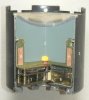
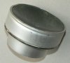
Cutaway model of a Yugoslav KPOM magnetic influence anti-tank mine. The mine is air dispensed and delivered by the R262 artillery rocket of the Orkan MLRS which has a payload of 24 KPOM mines, and the M77 rocket of the OGANJ MLRS which has a payload of four KPOM mines.
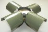
The mine is build up of a sheet steel outer casing (1), in which the explosive charge (2)and the magnetic infulence fuze housing (3) are placed. To the top of the outer casing the four retarding and orientation fins are placed. These pop out as soon as the mine has left the carrier housing of the rocket. In the base, a lead grid (4), packed in a sheet aluminium housing is placed. In my opinion it is meant to absorb the shock of impact on hard soil by deforming the lead. The mine in the casing is build up of a Self forming fragment (SFF) in top (5) http://en.wikipedia.org/wiki/Explosively_formed_penetrator , which functions according to the miznay-shardin effect. The 0,4 kg explosive charge (2) is packed in an aluminium container which is screwed into the green PVC fuze housing (3).
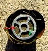
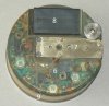
The greenPVC fuze housing contains the electronics (6) which are cast in transparent resign, the brass mechanical reduction gear box (7) housing the electric firing cap, the battery (8 ) and the metal detection spool (9 ).
As no descriptions of the mine are available in pamphlets, either on the internet, containing any detailed info, I have to make an educated guess as to some parts of the functioning of the mine.
Upon impact with the ground, an inertia switch is activated most probably in the mechanical reduction gear-, allowing the spring loaded mechanical reduction gear box to run down, rotating the last gearwheel which houses the electric firing cap under the detonator (10,red). It also releases a circuit breaker pin which allows the electric circuit to be closed (present, not visable in picture) , powering up the electric circuits. These form the arming delays after impact. When the detection spool (9) detects a large amount of metal passing over, it will activate the electric firing cap which will activate the detonator (red), igniting the main charge (2). This will form the concave steel disc (5) in top of the charge into a hypervelocity steel slug, that will penetrate the belly of a tank or an armoured vehicle. The required distance needed to form the slug is formed by the distance from the top of the mine to the belly of the tank.
-I do not know if there is a discrimination mechanism in the mine which can tell the difference between a tank, an armoured vehicle, a truck or a normal car. The relatively large amount of electronics makes me think it could possibly discriminate between a car and a tank.
-It is also unknown to me if the mine deactivates itself after a certain amount of hours by self destruct or if it is shut down and deactivated by the battery running out.
-Looking at the size of the battery and electronics, I guess at least 5 to 7 days of functioning can be expected, but thats a wild guess.
If anyone has more info about this mine, do not hesitate and let me know. Id be more than interested to learn more details.
Regards,DJH.
A Big thank you to Joop Dijkman from the MTM-DAWN (Munitie Technologisch Museum - Demining Academy Wanroy Netherlands) for allowing me to picture the loose parts of his mine (pict 04 and 05)
The mine is build up of a sheet steel outer casing (1), in which the explosive charge (2)and the magnetic infulence fuze housing (3) are placed. To the top of the outer casing the four retarding and orientation fins are placed. These pop out as soon as the mine has left the carrier housing of the rocket. In the base, a lead grid (4), packed in a sheet aluminium housing is placed. In my opinion it is meant to absorb the shock of impact on hard soil by deforming the lead. The mine in the casing is build up of a Self forming fragment (SFF) in top (5) http://en.wikipedia.org/wiki/Explosively_formed_penetrator , which functions according to the miznay-shardin effect. The 0,4 kg explosive charge (2) is packed in an aluminium container which is screwed into the green PVC fuze housing (3).
The greenPVC fuze housing contains the electronics (6) which are cast in transparent resign, the brass mechanical reduction gear box (7) housing the electric firing cap, the battery (8 ) and the metal detection spool (9 ).
As no descriptions of the mine are available in pamphlets, either on the internet, containing any detailed info, I have to make an educated guess as to some parts of the functioning of the mine.
Upon impact with the ground, an inertia switch is activated most probably in the mechanical reduction gear-, allowing the spring loaded mechanical reduction gear box to run down, rotating the last gearwheel which houses the electric firing cap under the detonator (10,red). It also releases a circuit breaker pin which allows the electric circuit to be closed (present, not visable in picture) , powering up the electric circuits. These form the arming delays after impact. When the detection spool (9) detects a large amount of metal passing over, it will activate the electric firing cap which will activate the detonator (red), igniting the main charge (2). This will form the concave steel disc (5) in top of the charge into a hypervelocity steel slug, that will penetrate the belly of a tank or an armoured vehicle. The required distance needed to form the slug is formed by the distance from the top of the mine to the belly of the tank.
-I do not know if there is a discrimination mechanism in the mine which can tell the difference between a tank, an armoured vehicle, a truck or a normal car. The relatively large amount of electronics makes me think it could possibly discriminate between a car and a tank.
-It is also unknown to me if the mine deactivates itself after a certain amount of hours by self destruct or if it is shut down and deactivated by the battery running out.
-Looking at the size of the battery and electronics, I guess at least 5 to 7 days of functioning can be expected, but thats a wild guess.
If anyone has more info about this mine, do not hesitate and let me know. Id be more than interested to learn more details.
Regards,DJH.
A Big thank you to Joop Dijkman from the MTM-DAWN (Munitie Technologisch Museum - Demining Academy Wanroy Netherlands) for allowing me to picture the loose parts of his mine (pict 04 and 05)
Attachments
-
 pict. 01 - Mine falling from air, baseview.jpg52.7 KB · Views: 102
 -
 pict. 02 - Top view mine.jpg49.7 KB · Views: 93
 -
 pict. 03 - Mine body cutaway with numbers.jpg79.7 KB · Views: 126
 -
 pict. 04 - Fuze housing.jpg69.1 KB · Views: 116
 -
 pict. 05 - EFP and explosive charge.jpg55.6 KB · Views: 89
 -
 pict. 06 - M-77 Oganj MLRS.jpg58.7 KB · Views: 83
 -
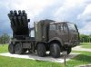 pict. 07 - M-87 Orkan MLRS.jpg48.3 KB · Views: 65
Last edited by a moderator: