What's new
British Ordnance Collectors Network

This is a sample guest message. Register a free account today to become a member! Once signed in, you'll be able to participate on this site by adding your own topics and posts, as well as connect with other members through your own private inbox!

Mills no5, 23 and 36, all marks.

It's worth pointing out that the No 5 was used with a rod as a rifle grenade from the spring of 1916 at least, possibly slightly earlier, but they were only used in volume from around August / September 1916 as the 23 Mk I. Sadly too late for the start of the Somme offensive.

John
 
Hi Norman

I've dug out my copy of L3579 and it's interesting to note that the 'II' is a hand annotation. So there was never a reprint to encompass the Mk II.

It looks like the idea progressed to a certain stage and then perhaps the changes Tom highlighted were integrated into normal production. I expect some base plugs were made in anticipation, but were probably just put on Mk I's.

John


John (and Tom),

Apologies for the delay in thanking you for this post. I have been without comms since Sunday due to a BT line fault.

Interesting remarks by Tom on the Centrepiece change and the cap chamber changes. In modern methodology design changes to the chamber would warrant an advance in Mark, but to the igniter set (ie Detonator) designation rather than the Grenade itself*. The change to the Centrepiece would justify an advance in Mark to the Grenade designation but if the change to the Centrepiece meant that some Marks of In-Service igniter sets were incompatible with the new design (thereby creating an Operational Variation) then it would be more appropriate to use a completely new number for the revised grenade.

Best

Norman

* however looking at one of my very old notebooks it seems that, against No 5 Mk II, I have written:
"Differs from the Mk I grenade only in design of cap" !!!
 
Hi Norman

Thanks for that post. I agree with you over the scope of changes and the potential for Mk up grade or not.

Tom's post about the gap problem also got me thinking about manufacturing inconsistency. So I dug out some aluminum No 5 centrepieces from my spares box and did some measuring. I measured the depth of the thread on the outside of the centrepiece at the same place, centred on the det tube. I used a digital Vernier calliper. The results were surprising.

Over 15 Centrepieces the depth varied all the time.

10.96 mm
10.37 mm
9.92 mm
9.75 mm
9.67 mm
9.66 mm
9.64 mm
9.54 mm
9.46 mm
9.42 mm
9.38 mm
9.36 mm
9.22 mm
8.85 mm
8.17 mm

I would have expected at least two to be the same in a mass produced item, but no. To find a difference of 2.79 mm between the largest and smallest was a surprise. It's not surprising the anvils rattled in some grenades.

Seeing that, I measured the same 15 centrepieces for overall length, as I hope that would be the same size. No, not one was the same as another, the longest being 70.44 mm and the shortest 67.40mm. A difference of over 3.4mm in a small sample.

Of course I can't state what No 5 or No 23 grenades these came from but the difference is I find quite staggering, when compared to say head spacing in rifles or machine guns. Mills always regarded his product as a well made 'luxury' weapon compared to say the German Stick grenade, but actually manufacturing standards seem pretty loose to me.

John
 
John,

Thanks for yours. Just to record the centrepiece lengths given in the engineering drawings:

No 5 - 23II High 2.73in (69.342mm) Low 2.71in (68.834mm)
No 23III - No 36 High 2.68in (68.072mm) Low 2.66in (67.564mm)
 
Thanks Norman

I can confirm that all the centrepieces I checked were from No 5's or 23 Mk I or II. None were 23 Mk III.

John
 
Thanks Norman

I can confirm that all the centrepieces I checked were from No 5's or 23 Mk I or II. None were 23 Mk III.

John


On the subject of centrepieces, why are some brass and some aluminium? I have a couple of number 5's with Brass, and an earlier one made from machined Aluminium. 8/16 and 10/16 brass, 6/16 Aluminium. all appear to be of same size.

Scott.
 
Almost from the start of production in 1915 Manufacturers were given options on materials for centre-pieces, filler screws and base plugs. That's why you can find examples of a the screws and base plugs in aluminium, brass, cast iron and steel. The No 23 Mk II moved base plug production to cast iron. Centre-pieces were made on aluminium, then brass, and in some cases a mixture of aluminium and copper (det tube). With the No 36 base plugs and centre-pieces were also made in mazak, which is a zinc based metal.

John

DSCN3058.jpg
 
Last edited:
A quick look at some of the specs suggests that the 'alternatives' were removed from the specification for the No 23 MkIII (& 23M MkIII) in February 1918 but prior to then five different CP constructions were allowed (but even within one method variations were allowed for instance copper det tube instead of brass).

Still looking for the Bakelite CP for the No 36 by the way.
 
Some Brass center tubes left to right, french copy mills cast tube, unknown semi cast, usual brass soldered variant.

HPIM0271.jpg HPIM0272.jpg

Lead and Brass tube examples

HPIM0273.jpg HPIM0274.jpg
 
I suppose it was a case of "austerity" and it was use what was available in supply/ease of manufacture in time of war. Noticed from my own collection that although the basic body shape was the same, through the series from No5 to 36M there was some variation in shape and size dependant on manufacturer, Odd that this being the case the 36M had a mark change to MkII when the lever support lugs changed. (Ive never seen a MkII that wasn't a practice version)
 
Now that's another debate. What is a 36 Mk II? Some will say it's just a plug change, others will say it's the plug plus the JPS Body with the extended shoulders.

I do have at least one of the JPS bodies with extended shoulders that are undrilled. They are around.

Regarding the different body shapes, I believe that manufacturers were supplied with the drawings they probably made a master then made moulds from that. As long as the general size and threads matched and the lever worked, they could say they had delivered what was required.

John
 
Last edited:
John,

Landers book mentions the reinforced shoulders in connection with the No 36 Mk II (Prac) implying that this feature was a part of the new design. You probably know that I wrote a fair bit of the book and I am sorry to say that there are a few errors, of which this is one and for which I take responsibility. I thought I was correct at the time and probably based it on something I had read but I have not been able to substantiate it since.

Nevertheless it was a good idea for the re-usable Practice grenade and JPS clearly thought so too.
 
Thanks for the reply Norman. It's a excellent book and I always put down anomalies in it to the editing!

Here's a photo of an undrilled JPS "Mk II" body. This one has an interesting history. I bought it from the son of a man who dropped into Arnhem in 44. After the war he went back on a visit for the anniversary service in 45. Whilst there a Dutch person gave him the grenade and said "You left this behind". He emptied it and brought it home. It still has most of the original finish.

John
 

Attachments

  • DSCN3060.jpg
    DSCN3060.jpg
    291.1 KB · Views: 38
Hi. This document was part of a series that was produced during WW2 to announce new designs or marks. Hopefully it is of interest. Cheers
 

Attachments

  • image.jpg
    image.jpg
    113.8 KB · Views: 53
Noticed that the shoulders are not extended in that drawing... confused as to what makes that a 36MkII?.
 
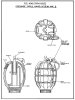
The approved change to No.36 Mark II, and noted in List of Changes paragraph 25114 in January 1922, is base plug and gas check only - bigger threaded hole in the one and bigger corresponding stud in the other.

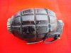
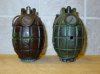
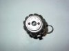
The swept lugs of the John Pilling & Sons casting appeared in 1940, and though they offer no mechanical advantage over the standard lugs, they seem to have become associated with the Mark II. One reason for this association may be simply that such JPS castings, with the five holes drilled in the body denoting practice grenade, are quite commonly found.

From 1939-42 JPS were the sole supplier of practice No.36 grenades . Pilling's first contract (294/G/4131, 29.12.39) for manufacture of grenades was for 20,000 Grenades, Hand, Practice, No.36 M Mark I. It is speculative that it was in order to further differentiate these Mark I practice grenades from Service items, Pilling took the decision to modify the lugs slightly.

Thereafter Pilling received reject bodies from other makers to turn into practice grenades, but even so, new bodies had to be cast to fulfil the orders. After supplying 200,000 practice Mark I up to December 1941, Pilling supplied a further 150,000 practice grenades with the Southern Engineering Group (SEG) Mark II base plug from January 1942 to September 1943.

While not formally an amendment or change for practice grenades, the association of the fluted lugs with practice grenades is understandable. That initially may have been a deliberate intent of the company John Pilling & Sons.

In June 1940 Pilling received the first order for 400,000 Service grenades, and up to March 1945 manufactured over 2.2 million. Many of these were also with the fluted lugs and still turn up - as seen above in John's post #35.


Tom.
 

Attachments

  • JPS bodies_2.jpg
    JPS bodies_2.jpg
    91.5 KB · Views: 39
  • DSC09876.jpg
    DSC09876.jpg
    76.2 KB · Views: 32
Tom

Thanks for your post. I think it's interesting that a) there was never a specification for the extended shoulders and b) there was only one manufacturer. This indicates that it was a local idea that clearly the War Office did not oppose it is it clearly made little difference to the basic design. What I do also find interesting is that the Mk II gas checks seem quite rare. I think I've only seen a couple over the last few years.

John
 
Top