As this posting contains a lot of pictures accompanying the text, pictures and partnumbers are described in the following way:
(P01-2 ) = (Picture 01-partnumber 2 ).
(P01, P04-2 ) = (Picture 01, Picture 04 -partnumber 2 ).
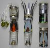
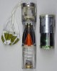
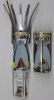
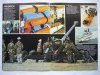
Cutaway model of two models bomblets as used in the BL-755 cluster bombs;
-the older type of bomblet - with the stainless steel coronet - ; the Bomblet HE, 1 Kg (2,15 Lb), No1, Mk1.
-the later(improved) type with the parachute retarder - ; the Bomblet HE, 1 Kg (2,15 Lb), No.2, Mk.1.
Both bomblets have the same double function;
-armor piercing (shaped charge) against hard skinned targets like tanks and armored vehicles. Penetration of the No.1 bomblet is 250mm, penetration of the No.2 bomblet is suspected to be around 300mm.
- Fragmentation against troop concentrations and soft skinned targets like transport vehicles , parked aircraft and anti-aircraft positions. The bomblet produces appr. 2000 square splinters
The bomblets are packed in the Bomb, cluster, 600 Lb with tail untit No.119 Mk1.
There are several versions of the Bomb:
- Bomb, cluster, 600 Lb, No.1 Mk.1 (superseded in service), uses the No.1 Mk1 Bomblets.
- Bomb, cluster, 600 Lb, No.1A Mk.1 (superseded in service), uses the No.1 Mk1 Bomblets.
- Bomb, cluster, 600 Lb, No.1 Mk.4, uses the No.1 Mk.1 Bomblets.
- Bomb, cluster, 600 Lb, No.2A Mk.1, uses the No.2 Mk.1 (parachute retarded) Bomblets.
- Bomb, cluster, 600 Lb, practice Nos 1 and 1Am Mk4, loaded with inert filled bomblets
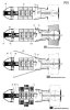
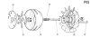
The Bomb, cluster, 600Lb description and functioning (P.01);
The Bomb, cluster, 600 Lb. is a free fall bomb comprising of a bomb body and a No. 119 Mk1 tail unit.
Inside the nose part of the bomb, the propeller (P01-01) driven Safety, Arming and Functioning Unit (SAFU) No.1 Mk2. (P01-02) is placed. Upon bomb release, a pull release wire (P01-03) is retracted from the SAFU, activating the SAFU. Behind the SAFU, the gas generator assembly (P01-04) is placed. The gas generator houses two gas pressure cartridges. The first gas pressure cartridge (P01-05) is firing pin activated by the SAFU, the second gas pressure cartridge (P01-06) is ignited later on by gas pressure of the first gas pressure cartridge. The gas generator housing has a number of holes drilled which lead the gas from the first pressure cartridge to two opposite sets of pistons and a firing pin piston. The first set of pistons (P01-07) have a wedge shaped edge which when moving outward- will pull two latches -connected to a rail alongside the bomb body- forward, unlocking the two skin pieces of the bomb body. The second set of pistons (P01-08 ), -being activated after the first set of pistons with the wedges have moved outward, opening a channel-, pushes the two skin pieces (P01-09) outward with force, removing the skin of the bomb body. When this second set of pistons moves outward it also releases a channel that launches a piston with a firing pin (P01-10) backward, igniting the second pressure cartridge (P01-06).
The gas pipe (P01-11) is placed into the back of the gas generator and forms the backbone of the bomb. It has six gas dustribution blocks (P01-12) each with seven ports in an circular array- placed over the pipe, as well as the bulkheads (or trays) between the bomblet packages. The first gas distribution block is connected to the back of the gas generator housing.
When the second pressure cartridge is ignited, a driving collar is pushed backward, breaking through shear plates, driving the gas tube backward, aligning the holes in the pipe with the holes in the gas distribution blocks.
Within the bomb body 147 bomblets are housed in a column of seven trays each containing 21 bomblets. Each tray is one of a circular array of 7 x 3 bombs, each placed in a Y shaped saddle, lined with an inflatable rubber bag (P01-13) (a kind of airbag), connected to a gas port of the gas distribution block (P01-12), used to throw the bomblets (P01-14) outward after the skin of the bomb is ejected. The ports leading to the rubber bags have different sized holes, causing each package of three bomblets to be ejected outward with a different speed, as the inflatable rubber bags expand with different speed. This is arrayed I such a way that a pattern of even distribution is enshured and bombs will not interfere upon ejection.
In the tail No.199 Mk1 four spring loaded fins are kept inward by a locking mechanism, to be released -to pop outward- by a pull wire (P01-15) upon bomb release. An interesting safety mechanism is built in the tail; a spring loaded gas release valve is placed in the back end of the gas pipe which runs from the distribution block to the back of the bomb, kept in opened position as long as the bomb tail is in unarmed position. Upon ejection of the bomb it is activated by a pull release wire (P01-16) and closes. In safe condition, the holes in the gas tube are not in line with the holes in the distribution blocks, and the base is now open (valve open), so in case of an accidental ignition of the first and secondary gas cartridges the skin is thrown off, but the pressure of the ejection cartridge is lead away through the valve(P1-5A) in the tail, not launching the bomblets.
On average, an oval footprint of 30x100 mtrs is covered by the bomblets.
Description of the Bomblet HE, 1 Kg (2,15 Lb), No1, Mk1.
The bomb is built up of the following main parts:
-The bomblet body.
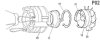
-The fuze assembly (pictures: P02,P03,P04 & P05)
-The spring loaded nose probe
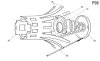
-The coronet; a tail piece that has twelve equally spaced tines on a cylindrical section. (P06)
-The bomblet body is made of prefragmentated 2,5 x 2,5 x 2,5mm squares wire that have been brassed together into a dome shaped fragmentation body. In the base of the fragmentation body the shaped charge red copper cone is roll crimped in place.
The explosive charge is a two piece charge: a RDX/TNT class A main charge, with a RDX booster pellet on top. The charges are separated by a paper disc.
(Pictures P02, P03, P05, P06)
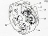
On top of the bomblet body, the cast and machined aluminum septum (Pict.02, 17) is roll crimped in place over the top of the bomblet body. In the center of the septum a hole is drilled, housing the stemming charge which ends on top of the booster charge. On top of the septum the safety and arming mechanism (P03) of the fuze is placed in a pressed aluminum ring (P05-8 ), held in place with a nylon circlip (P02-19) in a groove. The septum has a rim, over which the stator (P02-20) is shrunk in place. The stator controls the airflow over the rotor of the s&a unit and houses the coronet over the outer circumference.
(Pict. 02, 04)
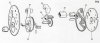
The s&a unit is built up of a top disc (P04-21) and bottom disc (P04-22) between which an electric firing cap is placed in a carrier wheel (P04-23) that rotates the electric firing cap in line with the stemming charge in the center of the septum. A clock spring (P04-24) is wound around the wheel, ready to rotate the wheel as soon as it is released. The rotation speed of the wheel is reduced by a reduction gear (P04-25) with an escapement (P04-26) that ensures a delay before the electric firing cap is rotated over the stemming section. The wheel is kept in fixated position by a release pin (P05-27) that fixates the wheel (P04-23), passes through the rotor (P05-28 ) and is connected to the end cap (P06-29). The spring (P05-30) loaded environmental sensing device detent pin (P05-31) is kept in lower position by the blind nut (P05-32) in the center of the rotor (P05-28 ). The inside of the rotor is serrated, being engaged by a two fingers threshold torque spring (P05,33), forming a mechanical threshold. The threshold torque spring ensures that if the airflow over the rotor is insufficient, the rotor will not rotate, and the bomb will not arm. When the bomb has a sufficient airflow over the rotor, it will overcome the torque force of the threshold spring, rotate, and fall off after five revolutions. On the inside of the upper disc of the s&a unit a thin disc (P04-34) with a printed circuit board is placed, facing downward; In safe position it short- circuits the electric firing cap, in armed position it places the electric firing cap in line with the electric firing circuit.
When in compressed position, the tines (P06-35) of the coronet (P06-36) are forced in inward position by the end cap (P06-29). Below the end cap a spring (P06-37) is placed that wants to push the endcap off, releasing the coronet tines and retracting the release pin (P05-27). This spring is supported by the support ring (P06-38 ). The end cap with the release pin, spring and support ring are fixated to one another.
The tips of the tines extend outward after release to approximately twice the body diameter. The coronet tines orientate the bombs probe forward on its descent to earth.
-The nose probe is build up of three pressed sheet metal probe legs that are locked in a base plate on the lower end. This baseplate houses a horse shoe shaped weight on a hinge that houses a piezo-electric element, packed in a retaining ring. The piezo-electric element is connected to a contact ring that is connected with the conical wound spring that pushes the nose probe outward. The upper end of the spring ends in a vertical wire that leads into the insulated receiver (P04-39) of the s&a unit.
The other side of the probe legs are split and have a triangular lock on the outside. When the spring has pushed out the nose probe, it fixates the legs in forward position.
Three rear stays (P06-40) run from the end cover to the lower end of the bomb where they are hooked over the lower edge of the bomb body.
The extended nose probe forms the stand-off, the optimum distance between base of cone and armor for maximum penetration.
Functioning of the bomblet:
After ejection from the main bomb body;
-The spring (P06-37) below the end cap (P06-29) immediately extends, forcing the coronet (P06-36) to move backward relative to the bomblet body until it reaches its working position. At the same moment, the release pin (P05-27) is withdrawn from the wheel (P04-23) and the rotor (P05-28 ), releasing both . The hooks on the stays (P06-40) shear off, completely releasing the end cap, allowing the coronet tines to expand. The complete set support ring, spring, end cap, stays, release pin- is caught by the airstream and blown away.
-At the moment the release pin is withdrawn, the wheel starts to rotate, reduced in speed by the reduction gear with escapement. The rotor starts rotating at the same moment and falls off after five revolutions, releasing the spring loaded environmental sensing device detent pin (P05-31) IF no more than 0,7 second has passed between the start of the wheel rotation and release of the environmental pin. This means that if the airflow is not fast enough to make 5 revolutions in 0,7 seconds and release the environmental pin, arming (air)speed is not reached and the s&a will not arm as the environmental pin is locked up by the end of an interrupted circular groove in the wheel. The minimum release speed for the BL755 is 500 km/hr (270 knots).
-At the moment the hooks of the stays break, the nose probe is released to move forward and lock in position.
-The bomb is now fully armed.
-Upon impact, the horseshoe shaped weight is hammered downward, compressing the piezo electric element, which gives off current. This current runs up the spring to the s&a unit, into the electric detonator in the wheel. This ignites the stemming section, the booster charge and the main charge.
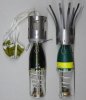
The Bomblet HE, 1 Kg (2,15 Lb), No.2, Mk.1. (newer type).
The main difference between the older type bomblet (bomblet HE, 1 Kg, No1, Mk1.described above) and the bomblet HE, 1 Kg, No.2, Mk.1 is the shape of the red copper shaped charge cone, allowing for a deeper armor penetration, and the coronet being replaced by a parachute retarder system.
The system works according to the same principals as the coronet with tines, however the coronet with tines has been replaced by a tail tube. This tail tube houses the retarder parachute just below the end cap. It is released when the end cap, spring, and support ring are thrown off.
-If a No.1 or No.2 Bomblet is found with the rotor still in place it is not armed.
-If a No.1 or No.2 Bomblet is found without the rotor it is to be considered armed and dangerous
-If a No.1 or No.2 Bomblet is found without the rotor but with the spring (P05-30) loaded environmental sensing device detent pin (P05-31) in place (but rotor away), the bomblet is not armed. However, if investigating the presence of the pin means movement of the Bomblet, it is simply to be considered armed and dangerous and to be handled as such.
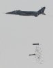
Some interesting you tube movies showing the BL755 in action:
Between 00:18 tm 00:27 seconds
https://www.youtube.com/watch?v=j4_CpSFIfwU
https://www.youtube.com/watch?v=42Wp-mSZ-Cs
Low order clearing of a BL-755 dud:
https://www.youtube.com/watch?v=QFpbb9bq8wE
Regards, DJH
(P01-2 ) = (Picture 01-partnumber 2 ).
(P01, P04-2 ) = (Picture 01, Picture 04 -partnumber 2 ).
Cutaway model of two models bomblets as used in the BL-755 cluster bombs;
-the older type of bomblet - with the stainless steel coronet - ; the Bomblet HE, 1 Kg (2,15 Lb), No1, Mk1.
-the later(improved) type with the parachute retarder - ; the Bomblet HE, 1 Kg (2,15 Lb), No.2, Mk.1.
Both bomblets have the same double function;
-armor piercing (shaped charge) against hard skinned targets like tanks and armored vehicles. Penetration of the No.1 bomblet is 250mm, penetration of the No.2 bomblet is suspected to be around 300mm.
- Fragmentation against troop concentrations and soft skinned targets like transport vehicles , parked aircraft and anti-aircraft positions. The bomblet produces appr. 2000 square splinters
The bomblets are packed in the Bomb, cluster, 600 Lb with tail untit No.119 Mk1.
There are several versions of the Bomb:
- Bomb, cluster, 600 Lb, No.1 Mk.1 (superseded in service), uses the No.1 Mk1 Bomblets.
- Bomb, cluster, 600 Lb, No.1A Mk.1 (superseded in service), uses the No.1 Mk1 Bomblets.
- Bomb, cluster, 600 Lb, No.1 Mk.4, uses the No.1 Mk.1 Bomblets.
- Bomb, cluster, 600 Lb, No.2A Mk.1, uses the No.2 Mk.1 (parachute retarded) Bomblets.
- Bomb, cluster, 600 Lb, practice Nos 1 and 1Am Mk4, loaded with inert filled bomblets
The Bomb, cluster, 600Lb description and functioning (P.01);
The Bomb, cluster, 600 Lb. is a free fall bomb comprising of a bomb body and a No. 119 Mk1 tail unit.
Inside the nose part of the bomb, the propeller (P01-01) driven Safety, Arming and Functioning Unit (SAFU) No.1 Mk2. (P01-02) is placed. Upon bomb release, a pull release wire (P01-03) is retracted from the SAFU, activating the SAFU. Behind the SAFU, the gas generator assembly (P01-04) is placed. The gas generator houses two gas pressure cartridges. The first gas pressure cartridge (P01-05) is firing pin activated by the SAFU, the second gas pressure cartridge (P01-06) is ignited later on by gas pressure of the first gas pressure cartridge. The gas generator housing has a number of holes drilled which lead the gas from the first pressure cartridge to two opposite sets of pistons and a firing pin piston. The first set of pistons (P01-07) have a wedge shaped edge which when moving outward- will pull two latches -connected to a rail alongside the bomb body- forward, unlocking the two skin pieces of the bomb body. The second set of pistons (P01-08 ), -being activated after the first set of pistons with the wedges have moved outward, opening a channel-, pushes the two skin pieces (P01-09) outward with force, removing the skin of the bomb body. When this second set of pistons moves outward it also releases a channel that launches a piston with a firing pin (P01-10) backward, igniting the second pressure cartridge (P01-06).
The gas pipe (P01-11) is placed into the back of the gas generator and forms the backbone of the bomb. It has six gas dustribution blocks (P01-12) each with seven ports in an circular array- placed over the pipe, as well as the bulkheads (or trays) between the bomblet packages. The first gas distribution block is connected to the back of the gas generator housing.
When the second pressure cartridge is ignited, a driving collar is pushed backward, breaking through shear plates, driving the gas tube backward, aligning the holes in the pipe with the holes in the gas distribution blocks.
Within the bomb body 147 bomblets are housed in a column of seven trays each containing 21 bomblets. Each tray is one of a circular array of 7 x 3 bombs, each placed in a Y shaped saddle, lined with an inflatable rubber bag (P01-13) (a kind of airbag), connected to a gas port of the gas distribution block (P01-12), used to throw the bomblets (P01-14) outward after the skin of the bomb is ejected. The ports leading to the rubber bags have different sized holes, causing each package of three bomblets to be ejected outward with a different speed, as the inflatable rubber bags expand with different speed. This is arrayed I such a way that a pattern of even distribution is enshured and bombs will not interfere upon ejection.
In the tail No.199 Mk1 four spring loaded fins are kept inward by a locking mechanism, to be released -to pop outward- by a pull wire (P01-15) upon bomb release. An interesting safety mechanism is built in the tail; a spring loaded gas release valve is placed in the back end of the gas pipe which runs from the distribution block to the back of the bomb, kept in opened position as long as the bomb tail is in unarmed position. Upon ejection of the bomb it is activated by a pull release wire (P01-16) and closes. In safe condition, the holes in the gas tube are not in line with the holes in the distribution blocks, and the base is now open (valve open), so in case of an accidental ignition of the first and secondary gas cartridges the skin is thrown off, but the pressure of the ejection cartridge is lead away through the valve(P1-5A) in the tail, not launching the bomblets.
On average, an oval footprint of 30x100 mtrs is covered by the bomblets.
Description of the Bomblet HE, 1 Kg (2,15 Lb), No1, Mk1.
The bomb is built up of the following main parts:
-The bomblet body.
-The fuze assembly (pictures: P02,P03,P04 & P05)
-The spring loaded nose probe
-The coronet; a tail piece that has twelve equally spaced tines on a cylindrical section. (P06)
-The bomblet body is made of prefragmentated 2,5 x 2,5 x 2,5mm squares wire that have been brassed together into a dome shaped fragmentation body. In the base of the fragmentation body the shaped charge red copper cone is roll crimped in place.
The explosive charge is a two piece charge: a RDX/TNT class A main charge, with a RDX booster pellet on top. The charges are separated by a paper disc.
(Pictures P02, P03, P05, P06)
On top of the bomblet body, the cast and machined aluminum septum (Pict.02, 17) is roll crimped in place over the top of the bomblet body. In the center of the septum a hole is drilled, housing the stemming charge which ends on top of the booster charge. On top of the septum the safety and arming mechanism (P03) of the fuze is placed in a pressed aluminum ring (P05-8 ), held in place with a nylon circlip (P02-19) in a groove. The septum has a rim, over which the stator (P02-20) is shrunk in place. The stator controls the airflow over the rotor of the s&a unit and houses the coronet over the outer circumference.
(Pict. 02, 04)
The s&a unit is built up of a top disc (P04-21) and bottom disc (P04-22) between which an electric firing cap is placed in a carrier wheel (P04-23) that rotates the electric firing cap in line with the stemming charge in the center of the septum. A clock spring (P04-24) is wound around the wheel, ready to rotate the wheel as soon as it is released. The rotation speed of the wheel is reduced by a reduction gear (P04-25) with an escapement (P04-26) that ensures a delay before the electric firing cap is rotated over the stemming section. The wheel is kept in fixated position by a release pin (P05-27) that fixates the wheel (P04-23), passes through the rotor (P05-28 ) and is connected to the end cap (P06-29). The spring (P05-30) loaded environmental sensing device detent pin (P05-31) is kept in lower position by the blind nut (P05-32) in the center of the rotor (P05-28 ). The inside of the rotor is serrated, being engaged by a two fingers threshold torque spring (P05,33), forming a mechanical threshold. The threshold torque spring ensures that if the airflow over the rotor is insufficient, the rotor will not rotate, and the bomb will not arm. When the bomb has a sufficient airflow over the rotor, it will overcome the torque force of the threshold spring, rotate, and fall off after five revolutions. On the inside of the upper disc of the s&a unit a thin disc (P04-34) with a printed circuit board is placed, facing downward; In safe position it short- circuits the electric firing cap, in armed position it places the electric firing cap in line with the electric firing circuit.
When in compressed position, the tines (P06-35) of the coronet (P06-36) are forced in inward position by the end cap (P06-29). Below the end cap a spring (P06-37) is placed that wants to push the endcap off, releasing the coronet tines and retracting the release pin (P05-27). This spring is supported by the support ring (P06-38 ). The end cap with the release pin, spring and support ring are fixated to one another.
The tips of the tines extend outward after release to approximately twice the body diameter. The coronet tines orientate the bombs probe forward on its descent to earth.
-The nose probe is build up of three pressed sheet metal probe legs that are locked in a base plate on the lower end. This baseplate houses a horse shoe shaped weight on a hinge that houses a piezo-electric element, packed in a retaining ring. The piezo-electric element is connected to a contact ring that is connected with the conical wound spring that pushes the nose probe outward. The upper end of the spring ends in a vertical wire that leads into the insulated receiver (P04-39) of the s&a unit.
The other side of the probe legs are split and have a triangular lock on the outside. When the spring has pushed out the nose probe, it fixates the legs in forward position.
Three rear stays (P06-40) run from the end cover to the lower end of the bomb where they are hooked over the lower edge of the bomb body.
The extended nose probe forms the stand-off, the optimum distance between base of cone and armor for maximum penetration.
Functioning of the bomblet:
After ejection from the main bomb body;
-The spring (P06-37) below the end cap (P06-29) immediately extends, forcing the coronet (P06-36) to move backward relative to the bomblet body until it reaches its working position. At the same moment, the release pin (P05-27) is withdrawn from the wheel (P04-23) and the rotor (P05-28 ), releasing both . The hooks on the stays (P06-40) shear off, completely releasing the end cap, allowing the coronet tines to expand. The complete set support ring, spring, end cap, stays, release pin- is caught by the airstream and blown away.
-At the moment the release pin is withdrawn, the wheel starts to rotate, reduced in speed by the reduction gear with escapement. The rotor starts rotating at the same moment and falls off after five revolutions, releasing the spring loaded environmental sensing device detent pin (P05-31) IF no more than 0,7 second has passed between the start of the wheel rotation and release of the environmental pin. This means that if the airflow is not fast enough to make 5 revolutions in 0,7 seconds and release the environmental pin, arming (air)speed is not reached and the s&a will not arm as the environmental pin is locked up by the end of an interrupted circular groove in the wheel. The minimum release speed for the BL755 is 500 km/hr (270 knots).
-At the moment the hooks of the stays break, the nose probe is released to move forward and lock in position.
-The bomb is now fully armed.
-Upon impact, the horseshoe shaped weight is hammered downward, compressing the piezo electric element, which gives off current. This current runs up the spring to the s&a unit, into the electric detonator in the wheel. This ignites the stemming section, the booster charge and the main charge.
The Bomblet HE, 1 Kg (2,15 Lb), No.2, Mk.1. (newer type).
The main difference between the older type bomblet (bomblet HE, 1 Kg, No1, Mk1.described above) and the bomblet HE, 1 Kg, No.2, Mk.1 is the shape of the red copper shaped charge cone, allowing for a deeper armor penetration, and the coronet being replaced by a parachute retarder system.
The system works according to the same principals as the coronet with tines, however the coronet with tines has been replaced by a tail tube. This tail tube houses the retarder parachute just below the end cap. It is released when the end cap, spring, and support ring are thrown off.
-If a No.1 or No.2 Bomblet is found with the rotor still in place it is not armed.
-If a No.1 or No.2 Bomblet is found without the rotor it is to be considered armed and dangerous
-If a No.1 or No.2 Bomblet is found without the rotor but with the spring (P05-30) loaded environmental sensing device detent pin (P05-31) in place (but rotor away), the bomblet is not armed. However, if investigating the presence of the pin means movement of the Bomblet, it is simply to be considered armed and dangerous and to be handled as such.
Some interesting you tube movies showing the BL755 in action:
Between 00:18 tm 00:27 seconds
https://www.youtube.com/watch?v=j4_CpSFIfwU
https://www.youtube.com/watch?v=42Wp-mSZ-Cs
Low order clearing of a BL-755 dud:
https://www.youtube.com/watch?v=QFpbb9bq8wE
Regards, DJH
Attachments
-
 01 - BL755 bomb functioning.jpg93.4 KB · Views: 139
 -
 02 - BL755 complete fuze assembly BL755.JPG22.8 KB · Views: 105
 -
 03 - BL755 assembled safety and arming mechanism BL755.jpg62.1 KB · Views: 111
 -
 04 - BL755 safety and arming fuze mechanism BL755.jpg74.5 KB · Views: 108
 -
 05 - BL755 environmental sensing unit s&a mechanim BL755.JPG30.8 KB · Views: 108
 -
 06 - BL755 No.1Mk.1 tail assemmbly.JPG35.8 KB · Views: 113
 -
 07 - BL755 No.1Mk.1 and BL755-No.2Mk1. unfolded cutaway models and fowlded models 4x.JPG154.1 KB · Views: 234
 -
 08 - BL755-No.2.Mk2 unfowlded cutaway model and folwded model.jpg150.6 KB · Views: 178
 -
 09 - BL755-No.1Mk.1 fowlded and unfowlded cutaway model.JPG141.5 KB · Views: 170
 -
 10 - BL755 No.1Mk.1 and BL755-No.2Mk1. unfolded backside cutaway model.JPG102.2 KB · Views: 152


")