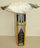
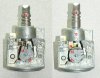
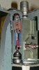
Cutaway model of a BLU-97A/B, BLU-97B/B CEM (Combined Effect Munitions) clusterbomb.
The BLU-97 is a small, aerially dispensed, decelerator stabilised, shaped charge, incendiary, anti-personel- and material clusterbomb.
It is used in the CBU-87 dispenser, which houses 202 BLU-97 A/B or BLU-97 B/B bombs, and the AGM-154A JSOW which houses 145 BLU-97/B bombs.
The bomb consists of the following main components;
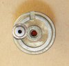
-The bomb body;
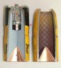
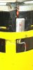
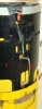
The bomb body (1) is a pressed carbon steel body which is tapered towards the top. The inside of the top hole is threaded to receive the fuze collar housing (5). The inside of the bomb body is pre-scored into 9x9 mm squares, the wall thickness is 4,2mm.
A 40 grams Zirconium ring (2) is placed just below the fuze can (6), in the explosive charge. In the centre of this ring a 2 grams RDX booster cilinder (3) is placed.
In the base, a red copper cone (4) with a top angle of 70 degrees is roll crimped in place.
-The fuze collar housing (5), the fuze (13), the support collar (9) . These three parts form the complete fuzing system.
The fuze collar housing (5) is a machined cast aluminium flange that forms the connection between fuze (13) and bomb body (1). It has the fuze can (6) -that houses the fuze mechanism- crimped around the base of the centre piece of the collar. At one point of the circumference a radial slot is machined, housing a Piezo-electric element (7) . A closing cap is pressed over te Piezo-electric element. A wire runs from this Piezo-electric element to a sliding contact (8 ) inside the fuze housing.
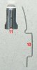
The plastic support collar (9) is positioned between the bomb body and the flange of the fuze collar housing. It houses the M55 stab detonator (12). The stab detonator is placed exactly below the piezo-electric element (7) in the fuze collar housing (5). Below the stab detonator (12) , the primary firing pin (10) is placed in the support collar. The point of the firing pin is kept away from the stab detonator by means of a safety clip (11).
The fuze (13) is an electro-mechanical fuze. It consists of a cast and machined fuze body (13) in which two fuze mechanisms are housed; the primary electrical-mechanical impact fuze, fed by the piezo electric element, and a separate mechanical all-ways fuze which acts when the primary fuzing system is not activated.
The primary electro-mechanical fuze uses an offline rotor (14) . A spring crank (15) is placed on the rotating shaft of the rotor. Between the rotor and the flange, a rotor spring (16) is placed. A small pin (17) is placed on the outer circumference of the spring crank, to which the main shaft (19 ) is connected by means of a yoke arm (18 ). At the end of the rotor shaft -protruding through the fuze housing- a small retainer cap (20) is crimped over the end of the shaft. At the other side of the rotor a short arc toothrack (21) is machined, which fits an escapement reduction gear (22).
The separate mechanical all-ways fuze is placed in a channel and fixated by a spring (23) loaded locking pin (24) that is kept in place by the retainer (20) cap on the spring crank shaft (15).
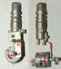
-The stand-off probe with the probe spring.
The Stand-off probe is a pressed steel can with a rim at the base, to retain the probe spring. In top of the can six square holes are cut out. These act as a catch for the six hooks of the stop clip (27), placed around the bomb body.
-The AID/RAD, and the AID/RAD canopy with latched wind tabs.
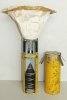
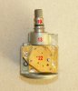
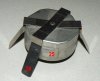
Two types of decelerator are in use, the round shaped AID (Attached Inflatable Decelerator) and the triangular RAD (Ram Air Decelerator). The decelerator has two purposes; orientating the clusterbomb nose forward, and arming of the fuze. The AID has been phased out due to high manufacturing costs compared to the RAD.
The AID/RAD canopy (25) is a stainless steel can, housing the AID/RAD. On top, two crossing latch strips (26) are riveted to the can. These latches grip behind the square holes in top of the stand-off probe. When placed in the CBU-87 body, the latches are kept in inward position by the plastic filler pieces, tightly filling the space between the bombs. As soon as the CBU dispenser body opens and the clusterbombs are dispersed, the airstream will bend the latches outward, unhooking from the holes in the stand-off probe. The probe spring will now be able to push the AID/RAD outward into employment.
Functioning of the bomb;
Upon release from the carrier, the airstream catches the crossing latch strips (26) and bends them outwards, unlatching the stainless steel AID/RAD canopy (25), allowing the canopy to move backward and fall away. The probe spring now starts pushing the bomb body backward until the hooks of the stop strip (27) fall through the square holes of the stand-off probe, fixating the bomb in it’s backward position in the stand-off probe.
At the same moment the safety clip (11), retaining the primary firing pin (10) falls away, allowing the firing pin to rotate 90 degrees outward, as well as allowing the firing pin to reach the M55 stab detonator (12) upon impact.
Also at the same moment the AID/RAD catches the airstream, and is deployed by air streaming into the air inlet ports. The deployed AID/RAD causes a pulling force on the main shaft (19) , which –when the force reaches 2,94 kg- is pulled backward 6mm by the deployed AID/RAD. The shaft is connected to the yoke arm (18 ) that also moves up 6mm, rotating the spring crank (15), tensioning the rotor spring (16) . This will force the off line rotor (14) to rotate the detonator in the centreline position, only to be slowed down –appr. 0,5 plm. 0,1 sec- in rotation speed by the escapement reduction gear (22). The detonator in the rotor (34, not in this picture) has a pin in the middle to which a sliding contact (8 ) from the Piezo-electric element connects. Upon impact , inertia pushes the bomb body down into the stand-off probe, pushing the firing pin (10) upward into the stab detonator (12) by means of the upper rim of the stand-off probe. The detonator explodes , pushing the aluminium above it upward, pressurizing the Piezo-electric element (7) which starts to generate current. This will detonate the electric firing cap in the rotor (34), the detonator below (35) it in the fuze housing, the RDX stemming charge (3) and the main charge, exploding the bomb.
When rotating the spring crank (15), the retainer cap (20) which keeps the spring (24) loaded locking pin (23) of the all ways fuze in inward position rotates, it releases the locking pin, arming the mechanical all-ways fuze. If the Electro-mechanical primary fuze does not function (mostly due to low impact angle, low speed or soft underground), the mechanical all-ways fuze should. After withdrawing the locking pin, the slider with the firing cap (30) is able to move up and down, the firing pin slider (31) above it, housing a spring loaded firing pin can move down. The firing pin is kept in a backward position by two small locking balls (32) that will release the firing pin to move into the firing cap when they are allowed move outward. If the bomb hits the ground, the top ball and the bottom inertia balls (33) will move down due to inertia, moving both sliders downward. The locking balls can now move outward , releasing the firing pin into the firing cap.
If the bomb falls on it’s side, the top ball (33) will be swung outward, being pushed downward when it rolls along the pointed top of the hole. This will push the firing pin slider (31) downward, releasing the small locking balls (32), releasing the firing pin into the firing cap. At the backside of the firing cap is a hole in machined in the slider, which connects to a hole in the rotor (14) -when rotated in armed postion-, allowing the flame of the detonator to reach the electric firing cap (34), exploding it. This will ignite the detonator (35) below it in the fuze housing, the RDX stemming charge (3) and the main charge, exploding the bomb.
Length stored: 16,8cm (6,6 inch).
Length deployed w/o AID or RAD: 22,6cm (8,9 inch).
Diameter: 63,5mm (2,5 inch).
Weight: 1,54 kg (3,4 lb).
Explosive charge: 287 grams Cyclotol 70/30 or 277 grams PBXN-107 (for insensitive munitions), as well as a 40 grams Zirconium incendiary ring. In the centre of this ring a 2 grams RDX cylinder is placed.
Penetration: 190mm steel.
The Blu-97 has been used in the first gulf war, in Afghanistan, Kosovo, and in Yemen by the Saudi air force according to the latest reports.
To give an idea with numbers: during the first Gulf war (1991) the US air force dropped 10.035 CBU-87 bombs on Iraqui targets, a total of 2.027.070 BLU-97 clusterbombs.
In Kosovo, about 1.100 CBU-87 bombs were dropped, a total of 222.200 BLU-97 clusterbombs.
Although the (design) calculated dud rate is between 1% minimum and 5% maximum, dud rates up to 30% have been reported. This is caused by several possible reasons;
-Too low dropping/opening height of the CBU-87. The fuze only fully arms after impact.
-Too fast or too slow dropping speed.
-Too long in storage (aging)
-Landing on soft targets (water, bushings, fine sand, high gras)
What makes the BLU-97 extremely dangerous as a dud is the primary firing pin (10) protruding outside the bomb body; upon insufficient impact the firing pin may have crept forward just piercing the M55 detonator sealing. The slightest tampering with this wire can set the bomb off. With the AID/RAD still attached wind gusts can move/roll the bomb, setting it off.
The mechanical all-ways fuze is very sensitive.
There is no render safe procedure for the BLU-97, so it has to be blown in situ, without touching it at all.
Regards, DJH
The BLU-97 is a small, aerially dispensed, decelerator stabilised, shaped charge, incendiary, anti-personel- and material clusterbomb.
It is used in the CBU-87 dispenser, which houses 202 BLU-97 A/B or BLU-97 B/B bombs, and the AGM-154A JSOW which houses 145 BLU-97/B bombs.
The bomb consists of the following main components;
-The bomb body;
The bomb body (1) is a pressed carbon steel body which is tapered towards the top. The inside of the top hole is threaded to receive the fuze collar housing (5). The inside of the bomb body is pre-scored into 9x9 mm squares, the wall thickness is 4,2mm.
A 40 grams Zirconium ring (2) is placed just below the fuze can (6), in the explosive charge. In the centre of this ring a 2 grams RDX booster cilinder (3) is placed.
In the base, a red copper cone (4) with a top angle of 70 degrees is roll crimped in place.
-The fuze collar housing (5), the fuze (13), the support collar (9) . These three parts form the complete fuzing system.
The fuze collar housing (5) is a machined cast aluminium flange that forms the connection between fuze (13) and bomb body (1). It has the fuze can (6) -that houses the fuze mechanism- crimped around the base of the centre piece of the collar. At one point of the circumference a radial slot is machined, housing a Piezo-electric element (7) . A closing cap is pressed over te Piezo-electric element. A wire runs from this Piezo-electric element to a sliding contact (8 ) inside the fuze housing.
The plastic support collar (9) is positioned between the bomb body and the flange of the fuze collar housing. It houses the M55 stab detonator (12). The stab detonator is placed exactly below the piezo-electric element (7) in the fuze collar housing (5). Below the stab detonator (12) , the primary firing pin (10) is placed in the support collar. The point of the firing pin is kept away from the stab detonator by means of a safety clip (11).
The fuze (13) is an electro-mechanical fuze. It consists of a cast and machined fuze body (13) in which two fuze mechanisms are housed; the primary electrical-mechanical impact fuze, fed by the piezo electric element, and a separate mechanical all-ways fuze which acts when the primary fuzing system is not activated.
The primary electro-mechanical fuze uses an offline rotor (14) . A spring crank (15) is placed on the rotating shaft of the rotor. Between the rotor and the flange, a rotor spring (16) is placed. A small pin (17) is placed on the outer circumference of the spring crank, to which the main shaft (19 ) is connected by means of a yoke arm (18 ). At the end of the rotor shaft -protruding through the fuze housing- a small retainer cap (20) is crimped over the end of the shaft. At the other side of the rotor a short arc toothrack (21) is machined, which fits an escapement reduction gear (22).
The separate mechanical all-ways fuze is placed in a channel and fixated by a spring (23) loaded locking pin (24) that is kept in place by the retainer (20) cap on the spring crank shaft (15).
-The stand-off probe with the probe spring.
The Stand-off probe is a pressed steel can with a rim at the base, to retain the probe spring. In top of the can six square holes are cut out. These act as a catch for the six hooks of the stop clip (27), placed around the bomb body.
-The AID/RAD, and the AID/RAD canopy with latched wind tabs.
Two types of decelerator are in use, the round shaped AID (Attached Inflatable Decelerator) and the triangular RAD (Ram Air Decelerator). The decelerator has two purposes; orientating the clusterbomb nose forward, and arming of the fuze. The AID has been phased out due to high manufacturing costs compared to the RAD.
The AID/RAD canopy (25) is a stainless steel can, housing the AID/RAD. On top, two crossing latch strips (26) are riveted to the can. These latches grip behind the square holes in top of the stand-off probe. When placed in the CBU-87 body, the latches are kept in inward position by the plastic filler pieces, tightly filling the space between the bombs. As soon as the CBU dispenser body opens and the clusterbombs are dispersed, the airstream will bend the latches outward, unhooking from the holes in the stand-off probe. The probe spring will now be able to push the AID/RAD outward into employment.
Functioning of the bomb;
Upon release from the carrier, the airstream catches the crossing latch strips (26) and bends them outwards, unlatching the stainless steel AID/RAD canopy (25), allowing the canopy to move backward and fall away. The probe spring now starts pushing the bomb body backward until the hooks of the stop strip (27) fall through the square holes of the stand-off probe, fixating the bomb in it’s backward position in the stand-off probe.
At the same moment the safety clip (11), retaining the primary firing pin (10) falls away, allowing the firing pin to rotate 90 degrees outward, as well as allowing the firing pin to reach the M55 stab detonator (12) upon impact.
Also at the same moment the AID/RAD catches the airstream, and is deployed by air streaming into the air inlet ports. The deployed AID/RAD causes a pulling force on the main shaft (19) , which –when the force reaches 2,94 kg- is pulled backward 6mm by the deployed AID/RAD. The shaft is connected to the yoke arm (18 ) that also moves up 6mm, rotating the spring crank (15), tensioning the rotor spring (16) . This will force the off line rotor (14) to rotate the detonator in the centreline position, only to be slowed down –appr. 0,5 plm. 0,1 sec- in rotation speed by the escapement reduction gear (22). The detonator in the rotor (34, not in this picture) has a pin in the middle to which a sliding contact (8 ) from the Piezo-electric element connects. Upon impact , inertia pushes the bomb body down into the stand-off probe, pushing the firing pin (10) upward into the stab detonator (12) by means of the upper rim of the stand-off probe. The detonator explodes , pushing the aluminium above it upward, pressurizing the Piezo-electric element (7) which starts to generate current. This will detonate the electric firing cap in the rotor (34), the detonator below (35) it in the fuze housing, the RDX stemming charge (3) and the main charge, exploding the bomb.
When rotating the spring crank (15), the retainer cap (20) which keeps the spring (24) loaded locking pin (23) of the all ways fuze in inward position rotates, it releases the locking pin, arming the mechanical all-ways fuze. If the Electro-mechanical primary fuze does not function (mostly due to low impact angle, low speed or soft underground), the mechanical all-ways fuze should. After withdrawing the locking pin, the slider with the firing cap (30) is able to move up and down, the firing pin slider (31) above it, housing a spring loaded firing pin can move down. The firing pin is kept in a backward position by two small locking balls (32) that will release the firing pin to move into the firing cap when they are allowed move outward. If the bomb hits the ground, the top ball and the bottom inertia balls (33) will move down due to inertia, moving both sliders downward. The locking balls can now move outward , releasing the firing pin into the firing cap.
If the bomb falls on it’s side, the top ball (33) will be swung outward, being pushed downward when it rolls along the pointed top of the hole. This will push the firing pin slider (31) downward, releasing the small locking balls (32), releasing the firing pin into the firing cap. At the backside of the firing cap is a hole in machined in the slider, which connects to a hole in the rotor (14) -when rotated in armed postion-, allowing the flame of the detonator to reach the electric firing cap (34), exploding it. This will ignite the detonator (35) below it in the fuze housing, the RDX stemming charge (3) and the main charge, exploding the bomb.
Length stored: 16,8cm (6,6 inch).
Length deployed w/o AID or RAD: 22,6cm (8,9 inch).
Diameter: 63,5mm (2,5 inch).
Weight: 1,54 kg (3,4 lb).
Explosive charge: 287 grams Cyclotol 70/30 or 277 grams PBXN-107 (for insensitive munitions), as well as a 40 grams Zirconium incendiary ring. In the centre of this ring a 2 grams RDX cylinder is placed.
Penetration: 190mm steel.
The Blu-97 has been used in the first gulf war, in Afghanistan, Kosovo, and in Yemen by the Saudi air force according to the latest reports.
To give an idea with numbers: during the first Gulf war (1991) the US air force dropped 10.035 CBU-87 bombs on Iraqui targets, a total of 2.027.070 BLU-97 clusterbombs.
In Kosovo, about 1.100 CBU-87 bombs were dropped, a total of 222.200 BLU-97 clusterbombs.
Although the (design) calculated dud rate is between 1% minimum and 5% maximum, dud rates up to 30% have been reported. This is caused by several possible reasons;
-Too low dropping/opening height of the CBU-87. The fuze only fully arms after impact.
-Too fast or too slow dropping speed.
-Too long in storage (aging)
-Landing on soft targets (water, bushings, fine sand, high gras)
What makes the BLU-97 extremely dangerous as a dud is the primary firing pin (10) protruding outside the bomb body; upon insufficient impact the firing pin may have crept forward just piercing the M55 detonator sealing. The slightest tampering with this wire can set the bomb off. With the AID/RAD still attached wind gusts can move/roll the bomb, setting it off.
The mechanical all-ways fuze is very sensitive.
There is no render safe procedure for the BLU-97, so it has to be blown in situ, without touching it at all.
Regards, DJH
Attachments
-
 P01 - BLU-97 AB -BB CEM with RAD.jpg139.5 KB · Views: 121
 -
 P02 - BLU-97 AB-BB CEM with AID extended and packed.JPG203.1 KB · Views: 103
 -
 P03 - BLU-97 AB-BB CEM backsides.JPG128.7 KB · Views: 93
 -
 P04 - BLU-97 AB-BB CEM Bomb body.JPG164.6 KB · Views: 131
 -
 P05 - Fuze in safe and armed condition.jpg294.5 KB · Views: 109
 -
 P06 - Reduction gear on fuze housing.JPG114.9 KB · Views: 93
 -
 P07 - Rotor, yoke and main shaft.JPG221.1 KB · Views: 94
 -
 P08 - base of fuze.JPG112.2 KB · Views: 81
 -
 P09 - Primary firing pin and safery clip.JPG65.6 KB · Views: 80
 -
 P10 - AID-RAD canopy.JPG87.4 KB · Views: 76
 -
 P11 - Primary firing pin safe.JPG121.2 KB · Views: 81
 -
 P12 - Primary firing pin armed.JPG106.3 KB · Views: 74
 -
 P13 - Mechanical all ways fuze.JPG49.5 KB · Views: 99
Last edited:
