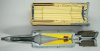
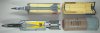
Cutaway model of a Russian BK-14M HEAT (High Explosive Anti Tank) shell, as used in the smooth barrelled 2A46 125mm gun of the T-72 Main battle tank. The shellcase and projectile are kept in two stacked ammo carousels below the bearing of the turret of the tank, the ammo horizontally stacked. The upper ring houses the projectiles, the lower ring houses the shellcases. If the gunner wants to load a certain type of ammo, he pushes a switchboard button with the designated type and the ammo carousel rotates the required type of ammo behind the breach. The loading automat will now push the projectile in the barrel, followed by the shellcase.
This means the T-72 does not have the need for a loader, reducing the crew from four to three. Another important advance was that -with the loader absent- one could build a much lower tank with a smaller silhouete. A big disadvantage however is that the munition was stacked quite open in the fighting compartiment of the tank, meaning that a direct hit often ends in an instantanious catastrofic ammunition explosion, completely blowing away the turret.
The BK-14M was the follow up of the Bk-12M HEAT which uses the I-238 electro mechanical impact fuze with a spit back detonator, igniting the detonator below the cone by means of a flame travelling down from the nose fuze detonator. The Bk-14M uses a closed circuit electrical fuzing system with fully insulated inner works, placed inside the projectile body. Also, the Bk12(M) uses a steel cone, the Bk-14M uses a red copper cone.
The complete cartridge (projectile + shellcase) is called 3BK 10 in the Russian nomenclature, The loose projectile : Bk-14M , the loose shellcase : 4Sh40.
The shellcase 4Sh40 of this cartridge is interesting because after firing only a short shellcase stub is ejected from the breech. The largest part of the shellcase wall is made of sheet powder that only ignites at a high temperature and pressure.
Description of the shellcase 4Sh40 :
The shellcase exists of a steel base part -140mm long- in which primer GUV-7 is screwed. The propulsion charge is placed in a combustable cilinder which is glued in the top of the base part. On top of the primer a bag of black powder is placed. This black powder charge quickly ignites the main charge. A charge of powdersticks is placed on top of the bag. Another bag of black powder is placed on top of the sticks. The surroundig space is filled with granular powder, kept in lower position by a combustable spacer. The powdercharge is closed by a combustable cap with a conical (chamfered) rim. This rim is meant to ease the loading with the loading automat.
The complete shellcase weighs 10 Kg, The steel base part weighs 3,4 Kg, the steel base part with the combustable shellcase wall and cap weighs 5 kg. This leaves 5 kg for the losse sticks, the granular powder and the black powder.
Description of the BK-14M HEAT projectile:
The projectile consists of three main parts: the projectile body, the nose piece and the tailpiece. The projectile body is a pressed and machined steel body, with a pipe piece to the base that is threaded internally to receive the V-15DU base fuze, and threaded externally to receive the tailpiece. The nosepiece is a cast and machined pipe piece with a threaded flange to the base that is screwed into the top of the body. It forms the stand-off, and houses the V-15PG electric generator fuze piece in top. It’s flange is slightly chamfered on the outside and it has a ring of notches on top of the flange to ease handling by the loading automat.
On the inside of the projectile body the copper cone is placed, to which a mirrored thin steel cone is brassed on top. In the base of the red copper cone a plug is placed that receives a spring loaded contact plug from V-15DU base fuze. In top, a spring loaded contact plug at the base of the V-15PG nose fuze is placed into the hole in top of the steel cone. Both cones, the explosive charge and the nose- and base fuze are electrically insulated from the outer projectile body and nose piece by means of a series of rubber, plastic and cartboard gasket rings and cups. This forms the inner and outer part of the electric circuit.
The explosive charge is build up of two separate pieces, the upper and lower part. The upper charge is placed around the red copper cone, the lower part houses the wave shaper and the hole in the base to receive the detonator charge (grey) of the V-15DU base fuze. The wave shaper is a piece of inert material (Bakelite), placed in the explosive charge to force the explosion wave to hit the red copper cone at a more preferable angle, enhancing penetration up to 10% compared to when no wave shaper is used.
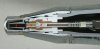
The V-15PG electric generator fuze piece is build-up of an aluminium (1) housing with an insulated connection plug (2) in the centre. On top of the connection plug a piezo-electric element (3) is placed. On top of the element pusher plate is placed (4) , locked up by an impact probe (5) screwed to the top of the fuze. Upon impact the impact probe is hammered inward, crushing the piezo-electric element which starts delivering an electric current when under pressure. The current flows down through the contact plug and through both cones into the contact plug (6) of the V-15DU base fuze.
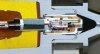
The V-15DU base fuze is build up of an insulated fuze housing (7) in which an aluminium fuze body (8 ) with the safety slider (9) is placed. In safe position, the electric firing cap (10) is placed out of line with the detonator (11) above. A spring (12) wants to move the slider under the detonator. However, in safe position the electric firing cap in the slider is placed in a short circuit position so it cannot be activated. A spring loaded contact plug (13) is placed in the base of the electric firing cap. Two mirrored V-grooves are machined in the longitudal direction in the middle of the slider, keeping the slider locked in safe position by means of a steel ball (14) in each groove.
Upon firing, a spring loaded inertia pin (15) moves back by set back, allowing the first ball to fall outward and release the slider. This forms the transport safety.
The opposite ball is pressed inward by a spring loaded inertia set back pin, fixating the slider. When the acceleration decreases after leaving the barrel, the spring pushes the inertia weight upward, releasing the second ball to fall out of the groove, releasing the spring loaded slider to slide the electric firing cap under the detonator. This forms the firing safety. Upon impact, the electric current will ignite the electric detonator, igniting the booster charge and the main charge.
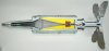
The tailpiece has six fins that pop out after leaving the barrel. As the barrel is smooth bore, and does not induce spin, fins are needed to stabilize the projectile during flight. A set-back ring keeps the fins fixated inward before firing.
Data:
Weight projectile: 19 kg.
Length complete cartridge (projectile placed on shellcase) 1084 mm.
Projectile length: 675 mm.
Diameter: 125 mm.
Vo : 905 mtrs/s
Explosive charge: 1,62kg charge, 75%HMX and 25%TNT.
Penetration : 450mm at 0 degrees.
Regards, DJH
Note: The “combustable” outside of shellcase and projectile are cartboard replica’s and do not form a fire hazzard.
This means the T-72 does not have the need for a loader, reducing the crew from four to three. Another important advance was that -with the loader absent- one could build a much lower tank with a smaller silhouete. A big disadvantage however is that the munition was stacked quite open in the fighting compartiment of the tank, meaning that a direct hit often ends in an instantanious catastrofic ammunition explosion, completely blowing away the turret.
The BK-14M was the follow up of the Bk-12M HEAT which uses the I-238 electro mechanical impact fuze with a spit back detonator, igniting the detonator below the cone by means of a flame travelling down from the nose fuze detonator. The Bk-14M uses a closed circuit electrical fuzing system with fully insulated inner works, placed inside the projectile body. Also, the Bk12(M) uses a steel cone, the Bk-14M uses a red copper cone.
The complete cartridge (projectile + shellcase) is called 3BK 10 in the Russian nomenclature, The loose projectile : Bk-14M , the loose shellcase : 4Sh40.
The shellcase 4Sh40 of this cartridge is interesting because after firing only a short shellcase stub is ejected from the breech. The largest part of the shellcase wall is made of sheet powder that only ignites at a high temperature and pressure.
Description of the shellcase 4Sh40 :
The shellcase exists of a steel base part -140mm long- in which primer GUV-7 is screwed. The propulsion charge is placed in a combustable cilinder which is glued in the top of the base part. On top of the primer a bag of black powder is placed. This black powder charge quickly ignites the main charge. A charge of powdersticks is placed on top of the bag. Another bag of black powder is placed on top of the sticks. The surroundig space is filled with granular powder, kept in lower position by a combustable spacer. The powdercharge is closed by a combustable cap with a conical (chamfered) rim. This rim is meant to ease the loading with the loading automat.
The complete shellcase weighs 10 Kg, The steel base part weighs 3,4 Kg, the steel base part with the combustable shellcase wall and cap weighs 5 kg. This leaves 5 kg for the losse sticks, the granular powder and the black powder.
Description of the BK-14M HEAT projectile:
The projectile consists of three main parts: the projectile body, the nose piece and the tailpiece. The projectile body is a pressed and machined steel body, with a pipe piece to the base that is threaded internally to receive the V-15DU base fuze, and threaded externally to receive the tailpiece. The nosepiece is a cast and machined pipe piece with a threaded flange to the base that is screwed into the top of the body. It forms the stand-off, and houses the V-15PG electric generator fuze piece in top. It’s flange is slightly chamfered on the outside and it has a ring of notches on top of the flange to ease handling by the loading automat.
On the inside of the projectile body the copper cone is placed, to which a mirrored thin steel cone is brassed on top. In the base of the red copper cone a plug is placed that receives a spring loaded contact plug from V-15DU base fuze. In top, a spring loaded contact plug at the base of the V-15PG nose fuze is placed into the hole in top of the steel cone. Both cones, the explosive charge and the nose- and base fuze are electrically insulated from the outer projectile body and nose piece by means of a series of rubber, plastic and cartboard gasket rings and cups. This forms the inner and outer part of the electric circuit.
The explosive charge is build up of two separate pieces, the upper and lower part. The upper charge is placed around the red copper cone, the lower part houses the wave shaper and the hole in the base to receive the detonator charge (grey) of the V-15DU base fuze. The wave shaper is a piece of inert material (Bakelite), placed in the explosive charge to force the explosion wave to hit the red copper cone at a more preferable angle, enhancing penetration up to 10% compared to when no wave shaper is used.
The V-15PG electric generator fuze piece is build-up of an aluminium (1) housing with an insulated connection plug (2) in the centre. On top of the connection plug a piezo-electric element (3) is placed. On top of the element pusher plate is placed (4) , locked up by an impact probe (5) screwed to the top of the fuze. Upon impact the impact probe is hammered inward, crushing the piezo-electric element which starts delivering an electric current when under pressure. The current flows down through the contact plug and through both cones into the contact plug (6) of the V-15DU base fuze.
The V-15DU base fuze is build up of an insulated fuze housing (7) in which an aluminium fuze body (8 ) with the safety slider (9) is placed. In safe position, the electric firing cap (10) is placed out of line with the detonator (11) above. A spring (12) wants to move the slider under the detonator. However, in safe position the electric firing cap in the slider is placed in a short circuit position so it cannot be activated. A spring loaded contact plug (13) is placed in the base of the electric firing cap. Two mirrored V-grooves are machined in the longitudal direction in the middle of the slider, keeping the slider locked in safe position by means of a steel ball (14) in each groove.
Upon firing, a spring loaded inertia pin (15) moves back by set back, allowing the first ball to fall outward and release the slider. This forms the transport safety.
The opposite ball is pressed inward by a spring loaded inertia set back pin, fixating the slider. When the acceleration decreases after leaving the barrel, the spring pushes the inertia weight upward, releasing the second ball to fall out of the groove, releasing the spring loaded slider to slide the electric firing cap under the detonator. This forms the firing safety. Upon impact, the electric current will ignite the electric detonator, igniting the booster charge and the main charge.
The tailpiece has six fins that pop out after leaving the barrel. As the barrel is smooth bore, and does not induce spin, fins are needed to stabilize the projectile during flight. A set-back ring keeps the fins fixated inward before firing.
Data:
Weight projectile: 19 kg.
Length complete cartridge (projectile placed on shellcase) 1084 mm.
Projectile length: 675 mm.
Diameter: 125 mm.
Vo : 905 mtrs/s
Explosive charge: 1,62kg charge, 75%HMX and 25%TNT.
Penetration : 450mm at 0 degrees.
Regards, DJH
Note: The “combustable” outside of shellcase and projectile are cartboard replica’s and do not form a fire hazzard.
Attachments
-
 01 - 125mm 3BK-10 HEAT cartridge.JPG244.4 KB · Views: 104
 -
 02 - 125mm BK-14M HEAT in flight.JPG152.9 KB · Views: 88
 -
 03 - 125mm Bk-14M HEAT V-15PG nose fuze.JPG196.9 KB · Views: 82
 -
 04 - 125mm BK-14M HEAT V-15DUbase fuze.JPG183.8 KB · Views: 76
 -
 05 - 125mm 3BK 10 HEAT and 125mm BM-15 APFSDS.JPG123.9 KB · Views: 96