As this posting contains a lot of pictures accompanying the text, pictures and partnumbers are described in the following way:
(P01-2 ) = (Picture 01-partnumber 2 ).
(P01, P04-2 ) = (Picture 01, Picture 04 -partnumber 2 ).
Aircraft bombs are meant to reduce or destroy the enemy’s war potential. Aircraft bombs do this by causing a shock wave, overpressure fragmentation and fire.
After World war 2 it became clear that the aircraft bombs in use were not suitable for the faster jet planes that were developed in the USA. This resulted in the development of the Mk-80 LDGP (Low Drag General Purpose)series aircraft bombs in the 1950s, producing less aerodynamic drag than the round nosed WW2 bombs.
The bomb shape was designed by Ed Heineman of the Douglas aircraft company and is known as the Aero 1A design. The length-diameter ratio is approximately 8:1.
Four bombs were developed in this range, -similar in shape and construction- ; the 250 pound Mk81, the 500 pound Mk-82, the 1000 pound Mk-83 and the 2000 pound Mk-84.
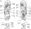
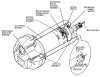
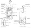
The bomb bodies are made of drawn an forged steel, with a threaded hole in the nose to receive the nose fuze well, which receives the nose fuze or the fuze extender, and a large hole in the base to receive the threaded base flange. The base fuze well is screwed into the base flange.
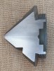
A ring with a machined V-groove is welded to the aft end of the bomb body to receive the mounting bolts for different types of bomb tails.
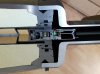
In top of the bomb body two thick plates are welded into two cut out holes. In these two plates three threaded holes are placed. The forward and afterward hole are blind threaded holes for the suspension lugs of the bomb.
The middle threaded hole has two holes in the bottom that connect to two question mark shaped thin walled steel pipes, one running from the middle hole of the bomb to the nose fuze well, one running from the middle hole to the tail fuze well. These pipes are meant to connect the forward and/or afterward electric fuzes to the FZU-48/B bomb fuze initiator (air flow generator) or the Mk-122 safety and arming switch by means of an electric cable, a steel pull wire to activate the firing pin activated battery of the FMU-81 /B nose or tail fuze, or an elastic cord to activate the FMU-54/B fuze.
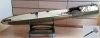
P01:
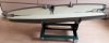
The bomb described in this posting is the 500 Lb Mk-82 in different versions.
The bomb body has a number of different fillings, with corresponding different type designations;
- The Mk-82 which is normally filled with 89 kgTritonal (80% TNT, 20% powdered aluminium), Minol (appr 40/45% TNT, 40/45% Ammonium nitrate and 10/20% aluminium powder) or Composition H6 (44% RDX, 29,5% TNT, 21% powdered aluminium, 5% parrafin wax and 0,5% Calcium Cloride).
-The BLU-111/B, which is filled with PBXN-109, a plastic bonded less sensitive explosive.
-The BLU-111A/B, which is filled with PBXN-109. The bomb has a thermal protective added coating to prevent it exploding within a certain time frame when in a fuel fire. It is meant for use on aircraft carriers by the navy only.
-The BLU-126/B, a BLU-111 with a smaller charge to prevent collateral damage. The rest of the bomb is filled with an inert filler to obtain the same drop trajectory.
-The BLU-129/B which has a tungsten laden carbon composite bomb body to reduce collateral damage due to blast and fragmentation radius.
-The Mark 62 Quickstrike mine. A naval mine derived from a Mk-82 bomb body.
-The Mk-82 mod.7 is a Mk-82 bomb body made from ductile cast iron that has a high fragmentation and uses a fuze that explodes the bomb at a certain height above the ground. This bomb is to replace clusterbombs in the future.
Mk-82 bomb body data:
Weight : 500 Lbs (241 kg). Thermal coating adds 14 kg (30 Lb) to the bomb body weight.
Explosives weight : 89 kg (192 Lbs) Trinotal , Minol II or H-6.
Diameter : 273mm.
Length : 1535mm.
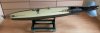
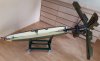
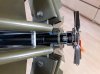
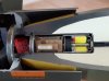
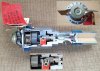
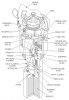
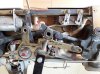
P02/P03/P04:
In picture 02 the normal Mk-82 LD (Low Drag) bomb is depicted, using a M904E2 nose fuze and/or a M095 tail fuze. It uses the MAU-93B fin set, which has an ATU-35 drive placed in the side of the cone of the tail when the M905 tail fuze is used. A hatch in the side of the tail is used to inspect the fuze and ATU drive flexible cable, either the arming wire of other suitable bomb fuze types running down from the hole in the top of the cone to the fuze.
This configuration of the Mk-82 is the most widely type used.
The nose fuze M094E2 is described in picture 26 & 27, the M905 tail fuze is described in picture 28 & 29.
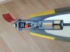
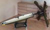
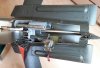
P05
Depicts the Mk-82 with the BSU-49 retarding tail. The BSU-49 is used mainly by the US air force for low level bombing. With low level bombing the risc of an airplane being hit –and downed- by it’s own bombs fragments is present. To avoid this, the bomb has a retarding ballute (the cross between a balloon and a parachute) which enables the airplane to escape it’s own fragmentation. The forward end of the tail has a steel ring with 8 radial placed hexagon socket set screws to connect the tail to the V-groove at the base of the bomb body.
The tail can also be used as a ‘normal’ bomb tail by not opening the ballute tail upon release, i twill than follow the trajectory of a ‘normal’ mk-82.
In this case, the bomb is fuzed with a M905 base fuze in combination with a ATU-35 drive assembly. A hatch in the side of the tail is used to inspect the fuze and ATU drive flexible cable, either the arming wire of other bomb fuze types running down from the hole in the top of the tail housing to the fuze.
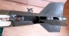
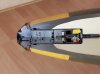
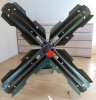
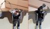
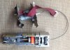
P06
The Mk-82 equiped with a Mk-15 Snakeye tail, called Mk-82 Snakeye. This tail is used mainly by the US navy and Marines for low level bombing. With low level bombing the risc of a plane being hit –and downed- by it’s own bombs fragments is present. To avoid this, the bomb uses four flip out brake petals to reduce the speed of the bomb, enabeling the plane to escape it’s own fragmentation.
The tail consists of a one piece cast and machined aluminium cover with a pipe that fits over the base of the bomb and uses eight Hexagon socket set screw to fixate this cover to the V-groove of the bomb body. the hinges of the petals is are placed in an aluminium profile that is screwd over the far end of the pipe. The four petals are connected by means of a sliding block that enshures all four petals move outward with the same speed, and also act as one side of the shock absorber, which prevents the tail of being ripped apart upon high speed release opening. This shock absorber is a corrugated aluminium pipe which is pushed inward 190 mm with 5 tons of force to absorb the shock.
In closed position the fins are kept inward by a spring loaded release band. The springs opening the tail petals are four leaf springs (one on the inside of each petal) that opens the fins just about 5 cm, enough to catch the airstream for further opening. The band is held in position by a lever, which is held in position by a coter pin. When withdrawn, the fins open and catch the airstream.
The fuze used is the M904E1 nose fuze. No fuze is placed in the base.
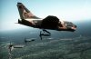
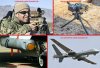
In picture 12 a Cosiar A7 can be seen, dropping Mk-82 Snakeye bombs.
P07:
The Fuze FMU-81 /B can also be used in this configuration , but as a nose fuze only. A descripion of this fuze can be found at pictures 37 & 38.
(P01-2 ) = (Picture 01-partnumber 2 ).
(P01, P04-2 ) = (Picture 01, Picture 04 -partnumber 2 ).
Aircraft bombs are meant to reduce or destroy the enemy’s war potential. Aircraft bombs do this by causing a shock wave, overpressure fragmentation and fire.
After World war 2 it became clear that the aircraft bombs in use were not suitable for the faster jet planes that were developed in the USA. This resulted in the development of the Mk-80 LDGP (Low Drag General Purpose)series aircraft bombs in the 1950s, producing less aerodynamic drag than the round nosed WW2 bombs.
The bomb shape was designed by Ed Heineman of the Douglas aircraft company and is known as the Aero 1A design. The length-diameter ratio is approximately 8:1.
Four bombs were developed in this range, -similar in shape and construction- ; the 250 pound Mk81, the 500 pound Mk-82, the 1000 pound Mk-83 and the 2000 pound Mk-84.
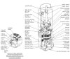
The bomb bodies are made of drawn an forged steel, with a threaded hole in the nose to receive the nose fuze well, which receives the nose fuze or the fuze extender, and a large hole in the base to receive the threaded base flange. The base fuze well is screwed into the base flange.
A ring with a machined V-groove is welded to the aft end of the bomb body to receive the mounting bolts for different types of bomb tails.
In top of the bomb body two thick plates are welded into two cut out holes. In these two plates three threaded holes are placed. The forward and afterward hole are blind threaded holes for the suspension lugs of the bomb.
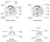
The middle threaded hole has two holes in the bottom that connect to two question mark shaped thin walled steel pipes, one running from the middle hole of the bomb to the nose fuze well, one running from the middle hole to the tail fuze well. These pipes are meant to connect the forward and/or afterward electric fuzes to the FZU-48/B bomb fuze initiator (air flow generator) or the Mk-122 safety and arming switch by means of an electric cable, a steel pull wire to activate the firing pin activated battery of the FMU-81 /B nose or tail fuze, or an elastic cord to activate the FMU-54/B fuze.
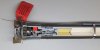
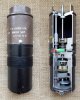
P01:
The bomb described in this posting is the 500 Lb Mk-82 in different versions.
The bomb body has a number of different fillings, with corresponding different type designations;
- The Mk-82 which is normally filled with 89 kgTritonal (80% TNT, 20% powdered aluminium), Minol (appr 40/45% TNT, 40/45% Ammonium nitrate and 10/20% aluminium powder) or Composition H6 (44% RDX, 29,5% TNT, 21% powdered aluminium, 5% parrafin wax and 0,5% Calcium Cloride).
-The BLU-111/B, which is filled with PBXN-109, a plastic bonded less sensitive explosive.
-The BLU-111A/B, which is filled with PBXN-109. The bomb has a thermal protective added coating to prevent it exploding within a certain time frame when in a fuel fire. It is meant for use on aircraft carriers by the navy only.
-The BLU-126/B, a BLU-111 with a smaller charge to prevent collateral damage. The rest of the bomb is filled with an inert filler to obtain the same drop trajectory.
-The BLU-129/B which has a tungsten laden carbon composite bomb body to reduce collateral damage due to blast and fragmentation radius.
-The Mark 62 Quickstrike mine. A naval mine derived from a Mk-82 bomb body.
-The Mk-82 mod.7 is a Mk-82 bomb body made from ductile cast iron that has a high fragmentation and uses a fuze that explodes the bomb at a certain height above the ground. This bomb is to replace clusterbombs in the future.
Mk-82 bomb body data:
Weight : 500 Lbs (241 kg). Thermal coating adds 14 kg (30 Lb) to the bomb body weight.
Explosives weight : 89 kg (192 Lbs) Trinotal , Minol II or H-6.
Diameter : 273mm.
Length : 1535mm.
P02/P03/P04:
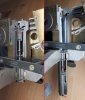
In picture 02 the normal Mk-82 LD (Low Drag) bomb is depicted, using a M904E2 nose fuze and/or a M095 tail fuze. It uses the MAU-93B fin set, which has an ATU-35 drive placed in the side of the cone of the tail when the M905 tail fuze is used. A hatch in the side of the tail is used to inspect the fuze and ATU drive flexible cable, either the arming wire of other suitable bomb fuze types running down from the hole in the top of the cone to the fuze.
This configuration of the Mk-82 is the most widely type used.
The nose fuze M094E2 is described in picture 26 & 27, the M905 tail fuze is described in picture 28 & 29.
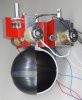
P05
Depicts the Mk-82 with the BSU-49 retarding tail. The BSU-49 is used mainly by the US air force for low level bombing. With low level bombing the risc of an airplane being hit –and downed- by it’s own bombs fragments is present. To avoid this, the bomb has a retarding ballute (the cross between a balloon and a parachute) which enables the airplane to escape it’s own fragmentation. The forward end of the tail has a steel ring with 8 radial placed hexagon socket set screws to connect the tail to the V-groove at the base of the bomb body.
The tail can also be used as a ‘normal’ bomb tail by not opening the ballute tail upon release, i twill than follow the trajectory of a ‘normal’ mk-82.
In this case, the bomb is fuzed with a M905 base fuze in combination with a ATU-35 drive assembly. A hatch in the side of the tail is used to inspect the fuze and ATU drive flexible cable, either the arming wire of other bomb fuze types running down from the hole in the top of the tail housing to the fuze.
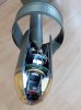
P06
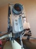
The Mk-82 equiped with a Mk-15 Snakeye tail, called Mk-82 Snakeye. This tail is used mainly by the US navy and Marines for low level bombing. With low level bombing the risc of a plane being hit –and downed- by it’s own bombs fragments is present. To avoid this, the bomb uses four flip out brake petals to reduce the speed of the bomb, enabeling the plane to escape it’s own fragmentation.
The tail consists of a one piece cast and machined aluminium cover with a pipe that fits over the base of the bomb and uses eight Hexagon socket set screw to fixate this cover to the V-groove of the bomb body. the hinges of the petals is are placed in an aluminium profile that is screwd over the far end of the pipe. The four petals are connected by means of a sliding block that enshures all four petals move outward with the same speed, and also act as one side of the shock absorber, which prevents the tail of being ripped apart upon high speed release opening. This shock absorber is a corrugated aluminium pipe which is pushed inward 190 mm with 5 tons of force to absorb the shock.
In closed position the fins are kept inward by a spring loaded release band. The springs opening the tail petals are four leaf springs (one on the inside of each petal) that opens the fins just about 5 cm, enough to catch the airstream for further opening. The band is held in position by a lever, which is held in position by a coter pin. When withdrawn, the fins open and catch the airstream.
The fuze used is the M904E1 nose fuze. No fuze is placed in the base.
In picture 12 a Cosiar A7 can be seen, dropping Mk-82 Snakeye bombs.
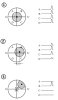
P07:
The Fuze FMU-81 /B can also be used in this configuration , but as a nose fuze only. A descripion of this fuze can be found at pictures 37 & 38.
Attachments
-
 P01 - 500 Lb Mk82 Bomb body.jpg262.2 KB · Views: 71
 -
 P02 - 500 Lb Mk82 GP bomb.jpg267.5 KB · Views: 71
 -
 P03 - Nose Fuze M904E2 in 500 Lb Mk82 bomb.jpg187.2 KB · Views: 71
 -
 P04 - Mk82 Mau 93-B fins detail.jpg203.2 KB · Views: 67
 -
 P05 Mk82 with BSU-49B high drag tail.jpg237.2 KB · Views: 65
 -
 P06 - Mk82 snakeye with nose Fuze M904E1.jpg239.5 KB · Views: 73
 -
 P07 - Nose or tail Fuze FMU-81b in Mk82 bomb.jpg182.9 KB · Views: 71
Last edited:

") .
.