What's new
British Ordnance Collectors Network

This is a sample guest message. Register a free account today to become a member! Once signed in, you'll be able to participate on this site by adding your own topics and posts, as well as connect with other members through your own private inbox!

Tins for Percussion Cap Mk111 & Fuze Percussion Bolt.

ron3350

Well-Known Member
I have two tins that I wish to know what the contents were and how they were used. Photos would help.

The hinged cap tin is army green with yellow print. Size is 70x50x20mm.

The Fuze Percussion -Bolt tin is 42mmx60mm.
The warning "not to be placed in the magazine on any pretence whatever" suggests something dangerous.

DSCN8538.jpgDSCN8534.jpgDSCN8535.jpgDSCN8536.jpgDSCN8537.jpg
 
The Fuze Percussion Bolt tin is very old and extremely rare; it's for the first of the "numbered series" of British fuzes which was introduced in 1885 and given it's number in 1887. I've attached a plate of the fuze. Depotman

FUZE PERCUSSION BOLT No 1 (Armstrong).jpg
 
A great reply Depotman. I have had this tin for 30 years and did not realise it meant Fuze No1, very early and great photo.
The Bolt part had me fooled completely. Does it mean the centre pin in the diagram? Now I have to find a fuze!! Thanks. Ron.
 
Hey Ron,

Well I have half of one!!! Hahaha

Cheers
Drew
 

Attachments

  • IMAG8413a.jpg
    IMAG8413a.jpg
    272.9 KB · Views: 26
  • IMAG8414a.jpg
    IMAG8414a.jpg
    283.1 KB · Views: 21
  • IMAG8415a.jpg
    IMAG8415a.jpg
    157.9 KB · Views: 19
Thanks Drew.
Half a fuze is better than none- a nice example. What shells used this fuze? I still do not understand the "bolt" part in fuse percussion-bolt.

Still no answer to what is a percussion cap mk111.
I found some tins on eBay but ID varies from PIAT mortar caps to British Army, Home guard to special forces.
What does it look like and how is it used please?
 
Hi Ron,

The attached extract from the "Treatie on Ammunition 1887" provides both a description of the bolt (part labelled "c") and the fuze operating functionality. I have highlighted the bolt in the diagram.

As stated, these Armstrong Bolt fuzes were issued to the Navy for their BL guns - doesn't specific which ones though.

Just curious how common or uncommon are these fuzes - any thoughts?

Cheers
Drew
 

Attachments

  • Armstrong Bolt-a.jpg
    Armstrong Bolt-a.jpg
    279.4 KB · Views: 17
  • Armstrong Bolt-c.jpg
    Armstrong Bolt-c.jpg
    232 KB · Views: 18
Last edited:
millsbomber
Thank you for the reference. If this is a snout it has no threads to screw into a switch and is called a percussion cap.
I have two different snouts in my collection but not the one shown.
What switch or device was it used in? I would like more information please.
 
Thank you everyone for the answers. I have the tapered snout for a mk111 igniter but not the stepped one in the SOE photo.
Obviously more than one style was made. I like learning new things.
 
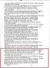
Tins for Percussion Cap Mk III & Fuze Percussion Bolt.

The rimmed snouts were the first generation and were used with Igniter Safety Fuze Percussion (ISFP). ISFPs were widely used by the Royal Engineers (RE) as a means of initiating Safety Fuze. When used in this role they were expected to remove the used snout and replace it with a fresh one which were issued separately in the tins shown. Obviously if they were used in booby traps this was not feasible.
ISFPs were used by RE in some of their own Anti-Tank Mines which were held by them and not RAOC. They were also used in RE improvised A/Tk mines, which they made up with any explosives they could lay their hands on.

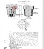
ISFPs were also used as the basis of Switches No 1 Pull and No2 Pressure. Switch No 3 only used the rimmed snout (see photo). The SOE photos are fairly indistinct. See photo showing the Switch No 3 striker pivoted out of the way to allow insertion of the rimmed snout. The other photo shows the tip of the striker which would help to keep the snout in position.

Eventually they were produced in numbers and became throwaway. The ISFP package photo refers to 1 and 2 which are probably for snouts. The actual package contains 20 x 10 tins of complete ISFPs. These tins had a Scored Tear Off strip (like a corned beef tin). Apparently over 350,000 were made in the 1950s, without the screw cap at the striker end.
There is also a watertight version of something very similar.

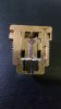
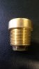
I include a photo of a Switch No 4 Pull, which shows the screwed snout. This was also used in Switches No 5 Pressure and 6 Release as well as the Time Pencils and 'L' Delay.

Despite the introduction of the Switch No 4 Pull, the RE continued to use the ISFP. For their purposes it is likely that the pin being pulled at right angle to the body enabled them to vary the strength of pull required and anchor it easily. I know from personal experience that the length of travel of the claw and Switch No 4 ball ended striker and the relative strength required to pull it against the already compressed spring, is considerable. The RE are laying mines and traps under the noses of the enemy and would need to be able to anchor the item easily which is difficult with the axial pull on a Switch No 4.


ISFP Mk III - description - 1.jpgISFP Mk III - package - 1.jpgISFP Mk III - rimmed snout - 1.jpgSwitch No 3 Release - 1.jpgSwitch No 3 Release - striker pivoted to allow rimmed snout - 1.jpgSwitch No 4 - Pull   screwed snout - 1.jpg
 
Last edited:
Top