Switch, No. 12 Release, Mk. I
Type- Release
Introduced 1943
Weight- 31.75 oz.
Length- 5.75 in.
Diameter- 3 in.
Filling- RDX/TNT 50/50
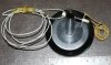
This switch was developed and manufactured by MD1 and introduced in 1943 as an anti-lift device to be placed under anti- tank mines. It was in fact a combination of the AP Switch (No. 8 Mk. I) and Pull Switch (No. 1 Mk. I). It was possible to use it as a boobytrap but such use was not recommended.
The switch was comprised of two main assemblies, the explosive container and the main housing tube. The explosive container was a shallow tapered drum (3” x ¾”) with an extension tube attached to the bottom but which passes completely through the container. It contained a charge of 4 ounces of RDX/TNT. The extension tube contains the firing mechanism consisting of a striker, firing pin spring and a bush at the bottom. The striker has a hollow spindle and is split at the bottom end. The main housing tube contains a retaining rod, lifting spring and has a flange at the top. The explosive container is held to the main housing tube by a self-trapping safety pin fitting through an eyelet on the base of the explosive container and a turned over portion of the flange on the main tube. A transit pin through the end of the safety pin ensures it does not come out accidentally. The safety pin has a steel wire attached to remove it after laying the device. A wooden plug closes the extension tube in storage and transit. The detonator assembly has a primer at the bottom end and two CE pellets.
When cocked, the extension tube fits into the main housing tube and compresses the lifting spring. The bottom of the striker is pushed through a hole in the centre of the bush and onto the retaining rod. The retaining rod enters the end of the hollow spindle pushing it open so that it cannot pass through the hole in the bush. The safety pin holds everything together.
When laid, the weight (at least 2.5 lbs) of the AT mine holds the head of the switch down. If the weight is not fully down on the switch the self -trapping safety pin cannot be removed. If the mine is lifted, the lifting spring forces the extension tube up and after about ¾ inch of travel the retaining rod is pulled out of the striker allowing it to pass through the hole in the bush. The striker spring then drives the striker up onto the primer. When the primer fires it causes the CE pellets to fire and in turn the main explosive filling of the device. In turn that will likely cause the AT mine to detonate.
The device is painted black with markings in white. The type of explosive is marked in yellow and in addition a red mark indicates a filled device.
Switch, No. 12 Release, Mk. 2
Introduced in 1960 the No. 12 Mk. 2 was very similar to the Mk.1 version. Differences included a slightly longer safety pin and changes to the filling. The single RDX/TNT pellet is replaced by an RDX/TNT 60/40 pellet perforated in the centre to accept a granulated CE initiating pellet. A plastic plug closes the extension tube.
The device is painted black with yellow markings.