As this posting contains a lot of pictures accompanying the text, pictures and partnumbers are described in the following way:
(P01-2 ) = (Picture 01-partnumber 2 ).
(P01, P04-2 ) = (Picture 01, Picture 04 -partnumber 2 ).
(P10) = full picture 10
Some text descriptions on the internet are hard to improve, and so quoted. This text is marked * text*
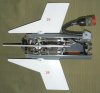
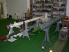
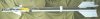
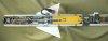
Cutaway model of both the AIM-B (P01) and AIM-9J (P015) Sidewinder short range air to air missile.
The design goal for the original Sidewinder missile (AIM-9B) was to produce a reliable and effective homing missile with the "electronic complexity of a table model radio and the mechanical complexity of a washing machine". Goals which were well accomplished in the early type missile (B-type). Later models of sidewinder became increasingly complex, and the current AIM-9X is shurely infenitely more complex than a table radio or a washing machine.
*Sidewinder is the common name of Crotalus cerastes, a venomous rattlesnake which uses infrared sensory organs to hunt warm-blooded prey. Early versions of the missile tended to perform zig-zagging course corrections during the early part of their flight path, following a trajectory that resembled the sidewinding motion of the snake.*
Introduction and history:
Even after WW2, the main armament of the fighter plane were machine guns and machine cannons. One of the problems with the new jet fighters was that with the increased speed and agility it became more difficult to get –and keep- any enemy plane long enough in the sight to enshure a lethal number of hits. One of the solutions was the revival of the Gatling gun in aircraft with a firing rate of 4200 rpm, but still, one had to keep the enemy in it’s sights in a high speed pursuit, both moving in three dimensions. At first, the US air force wanted a homing weapon that could destroy Sowjet bombers carrying nuclear bombs. That the weapon should destroy more than bombers became quite apparent during the Korean war, when the Russian build Mig-15’s formed an unexpected tough enemy for the American build F-86 Sabres. Both were cannon fighters, but the Mig-15 was lighter and more agile, causing US losses in the first months of the war. The US was able to keep the upper hand however by using battle hardened WW2 veteran pilots with much more experience than the pilots of the fledgling north Korean air force.
The US Air Force now wanted a weapon system that could engage the enemy from a longer distance and would guide itself to it’s target. The obvious choice was a missile. In 1949 a small team of scientists, led by Dr.Mclean started investigating the possibilities of a passive infra red homing system, with only limited financial resources. Another restriction was that all parts had to fit in a 5” tubular airframe, which was a major challenge in the days when vacuum tubes formed the main steering electronics. The result however was the earliest form of a functioning infra red heat seeking homing head. The conract to build these homing heads was awarded to the Philco company in 1951.
On the 11[SUP]th[/SUP] of September 1953, the first successful launch was made. This missile was designated XAAM-N7. In 1956 the missile was in the IOC stadium (In Operational Capebility)
The first time the Sidewinder (AIM-9B) was used in combat was in September 1958 when Chinese Nationalist F-86 Sabre’s fired the Sidewinder at communist Mig-17’s, downing eleven communist planes over the Formosa straight during the conflict.
However, the AIM-9B was only effective if the fighter was straight behind the tailpipe of the enemy plane – not head on or sideways, and only at a close range. It did not have the capability to be used with the earth’s surface as a background (clutter) behind the target. It did also have no nighttime capability. These problems however were quickly solved with subsequent models.
----------------------------------------------------------------------------------------------------------------------------------------
Description of functioning of the AIM-9B Sidewinder. (from a German instruction booklet)
With the AIM-9B the fighter pilot has a powerful weapon to engage enemy air targets with a speed below mach 2.5. After the passive target detection -while on the plane’s wing- the missile will steer itself to its target autonomously after launch by aiming at the infra red radiation of the exhaust of the enemy plane after launch.
A gyroscopic stabilized optical target seeker system is placed in the nose of the missile, keeping the centreline of the targeting mirror on the target constantly. When the target turns a corner, the electronics will deliver correcting signals to the steering fins to keep he missile on a collision course with the target.
When starting the engine of the airplane, generators ensure all electronic systems of the plane are powered up. The electronics and the gyroscopic Infra –red targeting system in the missile’s seeker head are also powered up at the same moment, bringing the gyroscopic mirror in the nose of the missile to a rotation of 4200 rpm, powered by the aircrafts electric power supply through the umbilical cable.
The missile is now ready to be used -searching for a target-, however as long as the missile is on it’s launching rail, a switch disconnects the targeting system from sending steering signals to the steering gear. In this condition, the gyroscopic stabilized optical target seeker system is fixated in such a way that the centreline of the targeting systems is kept in line with the centreline of the missile by means of a number of electric spools. Only targets that are off not more than 2 degrees with the missile’s centreline can be detected.
If -during the flight- the targeting system has locked to a target –which is possible up to a distance of 12 to 15 km with an optimal IR background- the pilot will hear a 840 Hz buzz tone through his headphone, informing him the missile seeker is locked to the target.
Upon firing the missile, the current in the electric spools which fixate the seeker are cut off, and the seeker head is able to swing outward 25 degrees in all directions so the seeker can keep track with a target that tries to evade the missile.
At the same moment, the gas generator cartridge is ignited, delivering the gas pressure for the pistons that rotate the steering fins, pressurizing the turbo generator as well. The turbo generator rotates at 1650 rpm, delivering 16,5 volts. As soon as the missile’s own generator is started, the current delivered by the plane is cut off, and the proximity fuze and the impact fuze are powered, as well as the motor ignition charge which is ignited.
Approximately 0,2 seconds after ignition of the motor, the missile overcomes the spring loaded locking pin in the launching rail, moving forward. In this process the umbilical cable is ripped of the missile body by shearing four M3 screws.
The turbo generator now powers all electric circuits in the missile. Approximately 0,4 to 0,5 seconds after the missile has left the launching rail, the switch which disconnects the targeting system from steering the fins is set over so the missile can be steered. Keeping the steering fins in a fixated position during this part of the flight is necessary as the missile has the tendency to over steer at speeds below Mach 0.8.
1.4 seconds after the missile leaves the launching rail, with both the impact and proximity fuze, the mechanical Safety and arming devices rotate and set the fuze to fully armed (disc rotated in line). The capacitor of the impact fuze starts loading when the umbilical cable is ripped off, loading the capacitor takes 0,5 seconds.
The proximity part of the fuze starts functioning (sending out light) 0,5 seconds after launch.
Upon direct impact with the target, the barium-trinitate crystals that are placed between the crossing points of the yokes are crushed when the steering fins are bend downward upon impact with the target. When crushed , the crystals deliver a 15 v current to the -already filled- impact fuze capacitor, causing the capacitor to discharge over the electric detonator circuit of the fuze, exploding the warhead.
When passing a target within 10 meters distance, the proximity fuze will ignite the electric detonator of the proximity fuze.
If the target is missed, the missile will self destruct in 27 to 28 seconds. The gas generator is burned up in 22 to 24 seconds, ending the steering corrections.
----------------------------------------------------------------------------------------------------------------------------------------
There are two ways a missile can be steered towards a target: by direct -or pure- pursuit (AIM-9B), and by proportional pursuit From AIM-9D onward).
-With direct or pure pursuit the missile is pointed/aimed directly at the target throughout the whole flight of the missile, eventually hitting the target. All evading movements of the target are corrected instantaneously in such a way that the missile points at the target again.
-With proportional pursuit the missile needs calculating power and an improved guidance algorithm. In this case the missile is not steered directly at the target, but to a point where it can be expected. It can be compared to giving lead when shooting a rifle on a right to left moving target. When a target tries to evade the missile, it will take the inside corner, trying to cut off and cross the target’s path. The proportional pursuit is much more effective than the direct pursuit, as it makes the missile “lead” the target. As the corners the missile with proportional pursuit has to take are much sharper, the AIM-9J has modified wings, with a rectangular wingtip, enabling the missile to take sharper corners.
AIM-9B:
Function : Air to Air missile.
Homing system : passive heatseeking (infra red).
Length : 2830mm
Diameter :130mm. (5 inch)
Motor : Thiokol Mk.17 solid single fuel stick motor.
Speed : mach 1.7
Range : 3,2 km
Launch weight : 70,4 kg
Wingspan : 559mm.
Warhead : Mk.8 Mod.4
Number produced : 80.900 pcs.
AIM-9J:
Function : Air to Air missile.
Homing system : passive heatseeking (infra red).
Length : 3070mm
Diameter :130mm. (5 inch)
Motor : Hercules/aerojet Mk.17 solid single fuel stick motor.
Range : 14,5 km
Speed : mach 2.5+
Launch weight : 80,7kg
Wingspan : 559mm.
Warhead : Mk.8 Mod.4
Number produced : 6.700 pcs ( AIM-9B type modified to E type, later upgraded to J type)
With the AIM-9B and the AIM-9J , both the Rocket motor, the proximity fuze and the warhead are the same. The parts that differ are the steering fins and actuators, the steering electronics and the infra-red homing seeker, in other words, all parts forward of the warhead.
The missile can be split up in six main parts:
1 - The infra red homing seeker
2 - The steering electronics
3 - The steering fins and actuators
4 - The Warhead with impact fuze
5 - The proximity fuze
6 - The motor
1 – The infra-red homing seeker (AIM-9B)
The infra-red homing seeker forms the nose part of the missile. It exists of cast resign pipe (P03-1), connected to the steering electronics part by means of six screws. In top the glass dome (P03-2) is glued in a rim. With the earlier models (AIM-9B) it was made of plain glass, later B types used a special type of glass that allowed infra-red light only to pass.
Below the dome, the spinning infra-red seeker (P03-3) is placed. It exists of a disc shaped concave mirror (P04-4) on a steel disc (P03-P04-5) that reflects the incoming infra red light to a flat, disc shaped mirror (P04-6) just below the dome (secondary mirror), facing the concave mirror. This mirror assembly is placed on a stem (P04-7) in the center of the concave mirror. This stem houses two bearings ; a double ball bearing (P04-8) to allow the mirror to spin with 70 rounds per second, and one ball and socket joint (P04-9) that allows the centerline of the mirror assembly to deviate from the missile’s centerline (P04-right picture).
Around the concave mirror disc, a number of electric phase coils is placed, cast in resign (P03-10). These coils form the stator of the motor rotating the mirror with 70 rounds per second, the steel disc (P04-5) below the concave mirror forms the rotor of the “motor”. Below these spools, another set of spools is cast in the resign, forming the precession coils (P03-11). These coils pull the centerline of the rotating mirror into the direction of the target (steered by the electronics below) by applying a magnetic force to one of the precession coils, trying to place the target in the center of the seeker (blind spot, no steering signal).
The infra-red light reflected from the flat mirror passes through the reticle disc(P03-12) and falls on the light sensitive photocell -PbS-cell- (P04-13 yellow), placed in a hole in the stem (P04-7). The reticle disc is placed between the flat mirror and the light sensitive photocell just above the light sensitive photocell.
PbS, or Lead(II)sulfide has semiconductor properties, which have long been recognized. PbS is one of the oldest and most common detection element materials in various infrared detectors. As an infrared detector, PbS functions as a photon detector, responding directly to the photons of radiation, as opposed to thermal detectors, which respond to a change in detector element temperature caused by the radiation. A PbS element can be used to measure radiation in either of two ways: by measuring the tiny photocurrent the photons cause when they hit the PbS material, or by measuring the change in the material's electrical resistance that the photons cause. Measuring the resistance change is the more commonly used method.At room temperature, PbS is sensitive to radiation at wavelengths between approximately 1 and 2.5 μm. This range corresponds to the shorter wavelengths in the infra-red portion of the spectrum, the so-called short-wavelength infrared (SWIR). Only very hot objects emit radiation in these wavelengths. Cooling the PbS elements, for example using liquid nitrogen or a Peltier element system, shifts its sensitivity range to between approximately 2 and 4 μm. Objects that emit radiation in these wavelengths still have to be quite hot -several hundred degrees Celsius- but not as hot as those detectable by uncooled sensors.
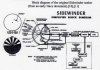
To understand the working of a reticle (P05-P06), we have to understand the way a missile sees a target. As a missile will always overtake its target -it is especially designed to do so-, the Z axis in the X,Y,Z Coordinate system is not important for both missile and target. The missile only sees a target moving over the X or Y axis. A plane for instance taking a sharp right turn right is seen as a dot of infra-red light, with an accelerating movement over the + X axis.
A reticle disc is a modulator that chops the scene, using transparent and opaque spokes on a spinning disc in front of the detector. The disc is 180 degrees opaque, the other 180 degrees exist of six sequentially arranged opaque and transparent spokes. The detector sees the scene chopped by the reticle at the spin rate of the reticle disc (70 rounds per second) times the number of spokes, known as carrier frequency. If an infra-red emitting target is –off line- in front of the seeker, the light arrives on the photo electric cell in the form of light pulses. The reticle design allows the sensor to detect when it is spinning past the zero point, allowing the angle of arrival of a target to be determined. The zero point is a fixed point, compared to which all course corrections are made. It tells the missile (P05, target position 1 and target position 2) at what radial position compared to the centerline of the missile the target is (between 0 and 360 degrees, or in other words; on which part of the full rotation of 360 degrees do the six pulses occur compared to the zero point). The amplitude of the pulses decide what the axial angle of deviation of the target is compared to the centerline of the missile.
The spokes are narrow near the centre, and become wider as they approach the outer circumference of the disc. Although the speed of the spokes of the reticle seeker is greater at the circumference than near the center, the angular speed of the spokes of the reticle is the same at the center and the circumference. The further the target is on the circumference of the spokes, the larger the amplitude of the signal, more to the center the amplitude of the signal is small.
The reticle also improves the signal to noise ratio by limiting the instantaneous field of view of the seeker. Small targets either targets far away are emphasized because they transmit the infra-red energy through a single transparent spoke. Large -or nearby- targets are minimized because the infra-red light is spread between transparent and opaque spokes. In the center of the nose cone there is a blind spot. If a target is in the blind spot (P05, target position 3), this means the missile is heading straight into the tailpipe of the target, so no signal is received, resulting in the missile following its last corrected course straight on.
The seeker head of the AIM-9B is not cooled, therefore it was it was easily misguided as the contrast between the target and the background was little. The improved German version of the AIM -9B, the AIM-9B FGW. Mk.2 had a replaceable bottle with 60 grams CO2 placed in the seeker head that cooled the infra-red seeker for appr. 2 hours, so creating a sharper contrast to the background, avoiding the missile losing the target.
1 – The infra-red homing seeker (AIM-9J)
The functioning of the infra-red seeker of the AIM-9J is generally the same as for the AIM-9B. However , the large and heavy seeker of the AIM- 9B was replaced by a smaller and lighter seeker (P17-14).
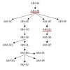
Unlike the US Navy, which was focussed on the tactical air battle, the USAF had diluted its resources into several Anti-Aircraft Missile programs and thus lagged in the development of their own Sidewinder subtypes. Vietnam saw the AIM-9B perform questionably, and the USAF sought improvements to the design to enhance performance against fighter type targets. The result was the AIM-9E. The AIM-9E saw the adoption of a similar low drag nose to the Navy subtypes, but using a conical rather than ogival profile, a distinguishing feature of this family to this very day. A Magnesium Fluoride dome was adopted, a more compact optical assembly was used, with a faster 100 Hz reticle rate, and a 16.5 deg/sec tracking rate. A black plastic container containing silica gel grains (P17-15) is used to keep the nosepiece free of moisture.
2 – The steering electronics (AIM-9B)
The steering electronics (P03-16) translate and filter the steering signals received from the optical target seeker system and translate it to a steering signal for the steering fins / canards. The electronics are cast in transparent silicon rubber to keep them dry and free from vibration. The AIM-9B uses vacuum tube technology.
2 – The steering electronics (AIM-9J)
The steering electronics translate and filter the steering signals received from the optical target seeker system and translate it to a steering signal for the steering fins / canards. The electronics are cast in transparent silicon rubber to keep them dry and free from vibration.
The follow-on version to the AIM-9E was the AIM-9J, which was rushed into the South East Asian theatre in July, 1972. The Juliet model saw incremental improvements to the AIM-9E design, with hybrid electronics using a mix of solid state and tube technology.
The most significant design change was the adoption of a cooling for the PbS detector element, the USAF opting for Peltier thermoelectric cooling (this missile). This arrangement has the advantage of unlimited cooling time on the launch rail, subject only to the availability of electrical power. The seeker improvements expanded the weapon's acquisition envelope and increased its, although not dramatically.
Over 5,000 rounds were rebuilt from AIM-9Bs.
The AIM-9J however still was tailpipe locking only, meaning it could only attack the enemy plane from behind. The first type of sidewinder to become “all aspect”- meaning it could also be launched at the side or front of an enemy plane was the AIM-9L.
3 – The steering fins and actuators (AIM-9B)
The steering fins and actuators are placed in a separate section of the missile, also housing the turbo generator (P07-17) -delivering current- and the Mod.0 gas generator cartridge (P03-18, gray). The umbilical cable (P03-19) connection is also placed in this section of the missile. When firing the missile, the gas generator is ignited and it starts delivering 71,4 bar (1000 psi) gas pressure for 22 to 24 seconds. The gas is lead through a number of filters to ensure no solid particles will foul up the cylinders (P03-20 or the generator scoop wheel (P07-21). The gas pressure serves the turbine generator which starts delivering current for the missile’s electric systems, as well as delivering a constant gas pressure on the four pistons (P03-22), placed in cylinders. Two opposite pistons each are placed on two crossing yokes (P03-23) -with opposite placed rocker arms on each yoke in which the piston rods (P03-24) swivel- to which the two opposite sets of steering fins are connected. This enables the canards to swing out 20 degrees to the left or right by means of varying the pressure in one or both sets of opposite cylinders, rotating one or both yokes. The four cylinders and the gas pressure cartridge are placed in a stainless steel divider flange (P03-25) which ensures all four cylinders are served with the exactly same pressure from the gas pressure cartridge, screwed in the centre of the flange, between the four cylinders. The pistons exist of a cylindrical steel housing in which a powerful solenoid (P03-26) is placed which forms a powerful magnet when electrically powered. A hole is drilled through the centre of the piston, ending in a small bleeding hole in top to allow gas to escape. On the base of the piston housing a hinged steel valve disc (P03-27) is placed, pulling the disc inward with force over the bleeding hole when the solenoid is powered, closing the bleeding hole. During the flight of the missile, the cylinders in which the pistons are placed are kept on 71,4 bar pressure to fixate them from any movement when no steering signal is received. This also means that with no steering all solenoids in the pistons are powered, so the valve disc is pulled inward to lock off the bleeding hole. When steering the missile, the electric power on one solenoid (or two solenoids when using a combined signal with two pistons) in the piston is either reduced, either turned off during a certain amount of time, allowing the gas to push away the disc and bleed gas through the bleeding hole. As the pressure drops in the cylinder, the pressure in the opposite yoke cylinder will rise relatively, pushing that piston upward, turning the rocker arms on the yoke and the set of canards connected to the yoke.
The canards of the AIM-9B have a triangular shape As the missile flies with it’s canards in the x position, serving one set of canards that is placed on either one of the legs of the x will result in the missile bending off 45 degrees up or down into the opposite side and mirrored for the other set of canards. So straight up is a combination of 45 degrees up left and 45 degrees up right. For this direction two magnet valves on the pistons have to be served at the same time (equal in pressure relieve and time open). This means that all course adjustments over purely over the X and Y axis exist of an equal combination signal by two pistons; changing course 45 degrees is done by actuating the valve disc of one of four pistons. Of course all angles between are proportional combination signals of two pistons.
3 – The steering fins and actuators (AIM-9J)
In general, the steering mechanism of the AIM-9J is the same as the AIM-9B, but with an improved control system using a longer burning –bigger- gas generator (P019-28) for a 40 sec flight time, and more powerful actuators delivering 90 lb.ft torque to the canard. The canards (P018-29) were changed to the characteristic squared tip double delta platform, adopted to improve canard behaviour at higher angles of attack. Significant changes were made to the internal wiring harnesses.
An interesting difference between the AIM-9B and the AIM-9J is the placement of the pistons and the cylinder flange. With the AIM-9B the flange is placed directly below the electronics, the pistons pointing forward. With the AIM-9J the stainless steel cylinder flange (P019-30) is placed in the lower portion of the steering fins and actuator housing. The pistons (P019-31 point backward. The magnetically served bleeding valves (P019-32) are placed on the top side of the piston. The solenoid is made of red copper windings (P019-33), the bleeding hole (P019-34) is in the center.
6,700 of this subtype were eventually built or rebuilt from AIM-9Bs.
4 – The Warhead Mk.8 Mod.4 (Same for AIM-9B and AIM-9J) (P09)
The Warhead Mk.8 Mod.4 is a11,3 kg explosive (fragmentation) warhead containing 4,77 kg HBX-1 (mixture of 38% TNT, 40% hexogen, 17% aluminum and 5% potassium chloride as binding agent) (P09-35).
It is build up of a steel pipe (P09-36) with a wall thickness of 5 mm. A steel flange is brassed is top (P09-37). This flange houses a long sheet metal bushing (P09-38) which houses the Mk.304 impact fuze and Mk.35 booster, the short bushing in the base (P09-39) houses the Mk.34 booster of the proximity fuze.
A cardboard liner (P09-40) is glued to the inside of the wall of the warhead. This liner has a regular hole pattern allowing the explosive charge to contact the steel wall i.w.o. the holes, but keeping the explosive charge free from the steel wall of the warhead with the rest of the liner. This enshures an even pattern in the distribution of the –between- 1200 to 1500 fragments. These fragments are able to penetrate a steel plate of 10mm or a 25mm aluminum plate at a distance of 10 meters. The blast working is lethal for a plane up to 3 meters. The total mass of these patterned fragments is 2,6 kg, the top and base of the warhead have a different fragmentation pattern. The fragments have a speed of 2000 mtrs/sec, measured 2 meters from the point of detonation. Upon detonation, the fragments do not only move outward, but also forward with a 6 to 8 degree angle from the perpendicular on the centerline of the missile.
Both in top and base -on the inside-, a groove (P09-41) is machined to connect the warhead with the proximity fuze (P10) and the steering fin housing (P03) by means of four U shaped clamps at 90 degr. each that fixate the sections of the missile.
Although the Mk.304 impact fuze (P08) is screwed to the base of the steering fins and actuators section (P03), it is considered a part of the warhead Mk.8 Mod.4 warhead. In top of the fuze housing four prolonged plugs (P08-42) electrically connect the fuze to the electric power circuit of the missile. When the fuze is placed in the base of the steering fins and actuators section, a hexagonal collar nut fixates it into position (P08-43). The upper part of the fuze housing contains electronics like capacitators, resistances, and induction spools (P08-44).
The lower part houses the mechanical S & A (safety & arming) device (P08-45). This device exists of an electrically activated detonator, placed in a disc (P08-46). The detonator in the disc is rotated off line with the Mk.35 booster (P08-47). The disc is fixated in this position by a spring loaded set back weight (P08-48)which is forked over a small pin in the side of the disc, and slowed in it’s rotating movement –once released- by a small reduction gear (P08-49). This forms the firing safety, ensuring the missile will be armed before having travelled 250 mtrs from the launching point. Upon firing, the set back weight “falls backward”, releasing the disc to rotate. A clock spring will now rotate the disc so the firing cap is placed in line (centerline missile) with the Mk.35 booster, arming the fuze.
Upon direct impact with the target, the barium-trinitate crystals that are placed between the crossing points of the yokes of the canards are crushed when the canards are bend downward upon impact with the target. When crushed , the crystals deliver a 15 v current to the -already filled- impact fuze capacitor (P08-50), causing the capacitor to discharge over the electric detonator circuit of the fuze (P08-51), exploding the warhead.
The detonator in the disc contains appr. 1 gram of Lead azide. The Mk.35 booster contains 34 grams of Tetryl.
5 – The Mk.303 proximity fuze. (Same for AIM-9B and AIM-9J) (P10)
The Mk.303 proximity fuze is meant to explode the warhead of the missile when passing the target within 10 meters without impact.
The fuze housing exists of an aluminum pot (P10-52). It is threaded on the outside at the base, enabling it to be screwed in the top of the motor. In top it has a groove (P10-53) on the inside to connect it to the warhead by means of four U shaped clamps. On the inside the fuze is divided as follows; in the base the electronics are placed, cast in transparent resign (P10-54). In the center a big capacitor (P10-55) is placed to serve the four light emitters (P10-56). On top of this, a ring shaped cage (P10-57) with four pairs of light emitters (P10-56) and light receivers (P10-58) is placed along the inner circumference of the fuze housing. Four pairs of square holes are cut out in an even array i.w.o. these light emitters and receivers around the circumference of the fuze body. A transparent plastic strip is glued over these holes, forming the window (P10-59).
In the center of this array the mechanical S&A mechanism is placed (P10-60), including the electrical-mechanical self- destruct mechanism (P10-61). This device exists of an electrically activated detonator, placed in a rotating safety disc (P10-62). The detonator in the disc is rotated off line with the Mk.34 (P10-63) booster when unarmed. The disc is fixated in this position by a spring loaded set back weight (P10-64)over a small pin on the disc, and slowed in it’s rotating movement –once released- by a small reduction gear (on the backside). This forms the inertia firing safety, ensuring the missile will not be armed before having travelled 250 mtrs from the launching point. Upon firing, the inertia set back weight “falls backward”, releasing the disc to rotate. A clock spring will now rotate the disc so the firing cap in the disc is placed in line (centerline missile) with the Mk.34 booster –closing an electric circuit as well-, arming the fuze.
The detonator in the disc contains appr. 1 gram of Lead azide. The Mk34 booster contains 35 grams of Tetryl.
The four light emitters send out light in a radial pattern, each covering 90 degrees of radius around the missile. If this light is bounced back to the receiver by an object that passes the missile within 10 meters of the missile, the electric resistance of the light sensitive resistance in the receiver will fall, enabling to pass an electric current to the electric detonator of the proximity fuze. Of course the wavelength of the light is chosen in such a way that this light does not appear naturally, and the receiver will react only on this type of wavelength.
(P01-2 ) = (Picture 01-partnumber 2 ).
(P01, P04-2 ) = (Picture 01, Picture 04 -partnumber 2 ).
(P10) = full picture 10
Some text descriptions on the internet are hard to improve, and so quoted. This text is marked * text*
Cutaway model of both the AIM-B (P01) and AIM-9J (P015) Sidewinder short range air to air missile.
The design goal for the original Sidewinder missile (AIM-9B) was to produce a reliable and effective homing missile with the "electronic complexity of a table model radio and the mechanical complexity of a washing machine". Goals which were well accomplished in the early type missile (B-type). Later models of sidewinder became increasingly complex, and the current AIM-9X is shurely infenitely more complex than a table radio or a washing machine.
*Sidewinder is the common name of Crotalus cerastes, a venomous rattlesnake which uses infrared sensory organs to hunt warm-blooded prey. Early versions of the missile tended to perform zig-zagging course corrections during the early part of their flight path, following a trajectory that resembled the sidewinding motion of the snake.*
Introduction and history:
Even after WW2, the main armament of the fighter plane were machine guns and machine cannons. One of the problems with the new jet fighters was that with the increased speed and agility it became more difficult to get –and keep- any enemy plane long enough in the sight to enshure a lethal number of hits. One of the solutions was the revival of the Gatling gun in aircraft with a firing rate of 4200 rpm, but still, one had to keep the enemy in it’s sights in a high speed pursuit, both moving in three dimensions. At first, the US air force wanted a homing weapon that could destroy Sowjet bombers carrying nuclear bombs. That the weapon should destroy more than bombers became quite apparent during the Korean war, when the Russian build Mig-15’s formed an unexpected tough enemy for the American build F-86 Sabres. Both were cannon fighters, but the Mig-15 was lighter and more agile, causing US losses in the first months of the war. The US was able to keep the upper hand however by using battle hardened WW2 veteran pilots with much more experience than the pilots of the fledgling north Korean air force.
The US Air Force now wanted a weapon system that could engage the enemy from a longer distance and would guide itself to it’s target. The obvious choice was a missile. In 1949 a small team of scientists, led by Dr.Mclean started investigating the possibilities of a passive infra red homing system, with only limited financial resources. Another restriction was that all parts had to fit in a 5” tubular airframe, which was a major challenge in the days when vacuum tubes formed the main steering electronics. The result however was the earliest form of a functioning infra red heat seeking homing head. The conract to build these homing heads was awarded to the Philco company in 1951.
On the 11[SUP]th[/SUP] of September 1953, the first successful launch was made. This missile was designated XAAM-N7. In 1956 the missile was in the IOC stadium (In Operational Capebility)
The first time the Sidewinder (AIM-9B) was used in combat was in September 1958 when Chinese Nationalist F-86 Sabre’s fired the Sidewinder at communist Mig-17’s, downing eleven communist planes over the Formosa straight during the conflict.
However, the AIM-9B was only effective if the fighter was straight behind the tailpipe of the enemy plane – not head on or sideways, and only at a close range. It did not have the capability to be used with the earth’s surface as a background (clutter) behind the target. It did also have no nighttime capability. These problems however were quickly solved with subsequent models.
----------------------------------------------------------------------------------------------------------------------------------------
Description of functioning of the AIM-9B Sidewinder. (from a German instruction booklet)
With the AIM-9B the fighter pilot has a powerful weapon to engage enemy air targets with a speed below mach 2.5. After the passive target detection -while on the plane’s wing- the missile will steer itself to its target autonomously after launch by aiming at the infra red radiation of the exhaust of the enemy plane after launch.
A gyroscopic stabilized optical target seeker system is placed in the nose of the missile, keeping the centreline of the targeting mirror on the target constantly. When the target turns a corner, the electronics will deliver correcting signals to the steering fins to keep he missile on a collision course with the target.
When starting the engine of the airplane, generators ensure all electronic systems of the plane are powered up. The electronics and the gyroscopic Infra –red targeting system in the missile’s seeker head are also powered up at the same moment, bringing the gyroscopic mirror in the nose of the missile to a rotation of 4200 rpm, powered by the aircrafts electric power supply through the umbilical cable.
The missile is now ready to be used -searching for a target-, however as long as the missile is on it’s launching rail, a switch disconnects the targeting system from sending steering signals to the steering gear. In this condition, the gyroscopic stabilized optical target seeker system is fixated in such a way that the centreline of the targeting systems is kept in line with the centreline of the missile by means of a number of electric spools. Only targets that are off not more than 2 degrees with the missile’s centreline can be detected.
If -during the flight- the targeting system has locked to a target –which is possible up to a distance of 12 to 15 km with an optimal IR background- the pilot will hear a 840 Hz buzz tone through his headphone, informing him the missile seeker is locked to the target.
Upon firing the missile, the current in the electric spools which fixate the seeker are cut off, and the seeker head is able to swing outward 25 degrees in all directions so the seeker can keep track with a target that tries to evade the missile.
At the same moment, the gas generator cartridge is ignited, delivering the gas pressure for the pistons that rotate the steering fins, pressurizing the turbo generator as well. The turbo generator rotates at 1650 rpm, delivering 16,5 volts. As soon as the missile’s own generator is started, the current delivered by the plane is cut off, and the proximity fuze and the impact fuze are powered, as well as the motor ignition charge which is ignited.
Approximately 0,2 seconds after ignition of the motor, the missile overcomes the spring loaded locking pin in the launching rail, moving forward. In this process the umbilical cable is ripped of the missile body by shearing four M3 screws.
The turbo generator now powers all electric circuits in the missile. Approximately 0,4 to 0,5 seconds after the missile has left the launching rail, the switch which disconnects the targeting system from steering the fins is set over so the missile can be steered. Keeping the steering fins in a fixated position during this part of the flight is necessary as the missile has the tendency to over steer at speeds below Mach 0.8.
1.4 seconds after the missile leaves the launching rail, with both the impact and proximity fuze, the mechanical Safety and arming devices rotate and set the fuze to fully armed (disc rotated in line). The capacitor of the impact fuze starts loading when the umbilical cable is ripped off, loading the capacitor takes 0,5 seconds.
The proximity part of the fuze starts functioning (sending out light) 0,5 seconds after launch.
Upon direct impact with the target, the barium-trinitate crystals that are placed between the crossing points of the yokes are crushed when the steering fins are bend downward upon impact with the target. When crushed , the crystals deliver a 15 v current to the -already filled- impact fuze capacitor, causing the capacitor to discharge over the electric detonator circuit of the fuze, exploding the warhead.
When passing a target within 10 meters distance, the proximity fuze will ignite the electric detonator of the proximity fuze.
If the target is missed, the missile will self destruct in 27 to 28 seconds. The gas generator is burned up in 22 to 24 seconds, ending the steering corrections.
----------------------------------------------------------------------------------------------------------------------------------------
There are two ways a missile can be steered towards a target: by direct -or pure- pursuit (AIM-9B), and by proportional pursuit From AIM-9D onward).
-With direct or pure pursuit the missile is pointed/aimed directly at the target throughout the whole flight of the missile, eventually hitting the target. All evading movements of the target are corrected instantaneously in such a way that the missile points at the target again.
-With proportional pursuit the missile needs calculating power and an improved guidance algorithm. In this case the missile is not steered directly at the target, but to a point where it can be expected. It can be compared to giving lead when shooting a rifle on a right to left moving target. When a target tries to evade the missile, it will take the inside corner, trying to cut off and cross the target’s path. The proportional pursuit is much more effective than the direct pursuit, as it makes the missile “lead” the target. As the corners the missile with proportional pursuit has to take are much sharper, the AIM-9J has modified wings, with a rectangular wingtip, enabling the missile to take sharper corners.
AIM-9B:
Function : Air to Air missile.
Homing system : passive heatseeking (infra red).
Length : 2830mm
Diameter :130mm. (5 inch)
Motor : Thiokol Mk.17 solid single fuel stick motor.
Speed : mach 1.7
Range : 3,2 km
Launch weight : 70,4 kg
Wingspan : 559mm.
Warhead : Mk.8 Mod.4
Number produced : 80.900 pcs.
AIM-9J:
Function : Air to Air missile.
Homing system : passive heatseeking (infra red).
Length : 3070mm
Diameter :130mm. (5 inch)
Motor : Hercules/aerojet Mk.17 solid single fuel stick motor.
Range : 14,5 km
Speed : mach 2.5+
Launch weight : 80,7kg
Wingspan : 559mm.
Warhead : Mk.8 Mod.4
Number produced : 6.700 pcs ( AIM-9B type modified to E type, later upgraded to J type)
With the AIM-9B and the AIM-9J , both the Rocket motor, the proximity fuze and the warhead are the same. The parts that differ are the steering fins and actuators, the steering electronics and the infra-red homing seeker, in other words, all parts forward of the warhead.
The missile can be split up in six main parts:
1 - The infra red homing seeker
2 - The steering electronics
3 - The steering fins and actuators
4 - The Warhead with impact fuze
5 - The proximity fuze
6 - The motor
1 – The infra-red homing seeker (AIM-9B)
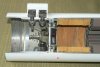
The infra-red homing seeker forms the nose part of the missile. It exists of cast resign pipe (P03-1), connected to the steering electronics part by means of six screws. In top the glass dome (P03-2) is glued in a rim. With the earlier models (AIM-9B) it was made of plain glass, later B types used a special type of glass that allowed infra-red light only to pass.
Below the dome, the spinning infra-red seeker (P03-3) is placed. It exists of a disc shaped concave mirror (P04-4) on a steel disc (P03-P04-5) that reflects the incoming infra red light to a flat, disc shaped mirror (P04-6) just below the dome (secondary mirror), facing the concave mirror. This mirror assembly is placed on a stem (P04-7) in the center of the concave mirror. This stem houses two bearings ; a double ball bearing (P04-8) to allow the mirror to spin with 70 rounds per second, and one ball and socket joint (P04-9) that allows the centerline of the mirror assembly to deviate from the missile’s centerline (P04-right picture).
Around the concave mirror disc, a number of electric phase coils is placed, cast in resign (P03-10). These coils form the stator of the motor rotating the mirror with 70 rounds per second, the steel disc (P04-5) below the concave mirror forms the rotor of the “motor”. Below these spools, another set of spools is cast in the resign, forming the precession coils (P03-11). These coils pull the centerline of the rotating mirror into the direction of the target (steered by the electronics below) by applying a magnetic force to one of the precession coils, trying to place the target in the center of the seeker (blind spot, no steering signal).
The infra-red light reflected from the flat mirror passes through the reticle disc(P03-12) and falls on the light sensitive photocell -PbS-cell- (P04-13 yellow), placed in a hole in the stem (P04-7). The reticle disc is placed between the flat mirror and the light sensitive photocell just above the light sensitive photocell.
PbS, or Lead(II)sulfide has semiconductor properties, which have long been recognized. PbS is one of the oldest and most common detection element materials in various infrared detectors. As an infrared detector, PbS functions as a photon detector, responding directly to the photons of radiation, as opposed to thermal detectors, which respond to a change in detector element temperature caused by the radiation. A PbS element can be used to measure radiation in either of two ways: by measuring the tiny photocurrent the photons cause when they hit the PbS material, or by measuring the change in the material's electrical resistance that the photons cause. Measuring the resistance change is the more commonly used method.At room temperature, PbS is sensitive to radiation at wavelengths between approximately 1 and 2.5 μm. This range corresponds to the shorter wavelengths in the infra-red portion of the spectrum, the so-called short-wavelength infrared (SWIR). Only very hot objects emit radiation in these wavelengths. Cooling the PbS elements, for example using liquid nitrogen or a Peltier element system, shifts its sensitivity range to between approximately 2 and 4 μm. Objects that emit radiation in these wavelengths still have to be quite hot -several hundred degrees Celsius- but not as hot as those detectable by uncooled sensors.
To understand the working of a reticle (P05-P06), we have to understand the way a missile sees a target. As a missile will always overtake its target -it is especially designed to do so-, the Z axis in the X,Y,Z Coordinate system is not important for both missile and target. The missile only sees a target moving over the X or Y axis. A plane for instance taking a sharp right turn right is seen as a dot of infra-red light, with an accelerating movement over the + X axis.
A reticle disc is a modulator that chops the scene, using transparent and opaque spokes on a spinning disc in front of the detector. The disc is 180 degrees opaque, the other 180 degrees exist of six sequentially arranged opaque and transparent spokes. The detector sees the scene chopped by the reticle at the spin rate of the reticle disc (70 rounds per second) times the number of spokes, known as carrier frequency. If an infra-red emitting target is –off line- in front of the seeker, the light arrives on the photo electric cell in the form of light pulses. The reticle design allows the sensor to detect when it is spinning past the zero point, allowing the angle of arrival of a target to be determined. The zero point is a fixed point, compared to which all course corrections are made. It tells the missile (P05, target position 1 and target position 2) at what radial position compared to the centerline of the missile the target is (between 0 and 360 degrees, or in other words; on which part of the full rotation of 360 degrees do the six pulses occur compared to the zero point). The amplitude of the pulses decide what the axial angle of deviation of the target is compared to the centerline of the missile.
The spokes are narrow near the centre, and become wider as they approach the outer circumference of the disc. Although the speed of the spokes of the reticle seeker is greater at the circumference than near the center, the angular speed of the spokes of the reticle is the same at the center and the circumference. The further the target is on the circumference of the spokes, the larger the amplitude of the signal, more to the center the amplitude of the signal is small.
The reticle also improves the signal to noise ratio by limiting the instantaneous field of view of the seeker. Small targets either targets far away are emphasized because they transmit the infra-red energy through a single transparent spoke. Large -or nearby- targets are minimized because the infra-red light is spread between transparent and opaque spokes. In the center of the nose cone there is a blind spot. If a target is in the blind spot (P05, target position 3), this means the missile is heading straight into the tailpipe of the target, so no signal is received, resulting in the missile following its last corrected course straight on.
The seeker head of the AIM-9B is not cooled, therefore it was it was easily misguided as the contrast between the target and the background was little. The improved German version of the AIM -9B, the AIM-9B FGW. Mk.2 had a replaceable bottle with 60 grams CO2 placed in the seeker head that cooled the infra-red seeker for appr. 2 hours, so creating a sharper contrast to the background, avoiding the missile losing the target.
1 – The infra-red homing seeker (AIM-9J)
The functioning of the infra-red seeker of the AIM-9J is generally the same as for the AIM-9B. However , the large and heavy seeker of the AIM- 9B was replaced by a smaller and lighter seeker (P17-14).
Unlike the US Navy, which was focussed on the tactical air battle, the USAF had diluted its resources into several Anti-Aircraft Missile programs and thus lagged in the development of their own Sidewinder subtypes. Vietnam saw the AIM-9B perform questionably, and the USAF sought improvements to the design to enhance performance against fighter type targets. The result was the AIM-9E. The AIM-9E saw the adoption of a similar low drag nose to the Navy subtypes, but using a conical rather than ogival profile, a distinguishing feature of this family to this very day. A Magnesium Fluoride dome was adopted, a more compact optical assembly was used, with a faster 100 Hz reticle rate, and a 16.5 deg/sec tracking rate. A black plastic container containing silica gel grains (P17-15) is used to keep the nosepiece free of moisture.
2 – The steering electronics (AIM-9B)
The steering electronics (P03-16) translate and filter the steering signals received from the optical target seeker system and translate it to a steering signal for the steering fins / canards. The electronics are cast in transparent silicon rubber to keep them dry and free from vibration. The AIM-9B uses vacuum tube technology.
2 – The steering electronics (AIM-9J)
The steering electronics translate and filter the steering signals received from the optical target seeker system and translate it to a steering signal for the steering fins / canards. The electronics are cast in transparent silicon rubber to keep them dry and free from vibration.
The follow-on version to the AIM-9E was the AIM-9J, which was rushed into the South East Asian theatre in July, 1972. The Juliet model saw incremental improvements to the AIM-9E design, with hybrid electronics using a mix of solid state and tube technology.
The most significant design change was the adoption of a cooling for the PbS detector element, the USAF opting for Peltier thermoelectric cooling (this missile). This arrangement has the advantage of unlimited cooling time on the launch rail, subject only to the availability of electrical power. The seeker improvements expanded the weapon's acquisition envelope and increased its, although not dramatically.
Over 5,000 rounds were rebuilt from AIM-9Bs.
The AIM-9J however still was tailpipe locking only, meaning it could only attack the enemy plane from behind. The first type of sidewinder to become “all aspect”- meaning it could also be launched at the side or front of an enemy plane was the AIM-9L.
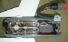
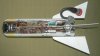
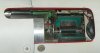
3 – The steering fins and actuators (AIM-9B)
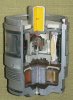
The steering fins and actuators are placed in a separate section of the missile, also housing the turbo generator (P07-17) -delivering current- and the Mod.0 gas generator cartridge (P03-18, gray). The umbilical cable (P03-19) connection is also placed in this section of the missile. When firing the missile, the gas generator is ignited and it starts delivering 71,4 bar (1000 psi) gas pressure for 22 to 24 seconds. The gas is lead through a number of filters to ensure no solid particles will foul up the cylinders (P03-20 or the generator scoop wheel (P07-21). The gas pressure serves the turbine generator which starts delivering current for the missile’s electric systems, as well as delivering a constant gas pressure on the four pistons (P03-22), placed in cylinders. Two opposite pistons each are placed on two crossing yokes (P03-23) -with opposite placed rocker arms on each yoke in which the piston rods (P03-24) swivel- to which the two opposite sets of steering fins are connected. This enables the canards to swing out 20 degrees to the left or right by means of varying the pressure in one or both sets of opposite cylinders, rotating one or both yokes. The four cylinders and the gas pressure cartridge are placed in a stainless steel divider flange (P03-25) which ensures all four cylinders are served with the exactly same pressure from the gas pressure cartridge, screwed in the centre of the flange, between the four cylinders. The pistons exist of a cylindrical steel housing in which a powerful solenoid (P03-26) is placed which forms a powerful magnet when electrically powered. A hole is drilled through the centre of the piston, ending in a small bleeding hole in top to allow gas to escape. On the base of the piston housing a hinged steel valve disc (P03-27) is placed, pulling the disc inward with force over the bleeding hole when the solenoid is powered, closing the bleeding hole. During the flight of the missile, the cylinders in which the pistons are placed are kept on 71,4 bar pressure to fixate them from any movement when no steering signal is received. This also means that with no steering all solenoids in the pistons are powered, so the valve disc is pulled inward to lock off the bleeding hole. When steering the missile, the electric power on one solenoid (or two solenoids when using a combined signal with two pistons) in the piston is either reduced, either turned off during a certain amount of time, allowing the gas to push away the disc and bleed gas through the bleeding hole. As the pressure drops in the cylinder, the pressure in the opposite yoke cylinder will rise relatively, pushing that piston upward, turning the rocker arms on the yoke and the set of canards connected to the yoke.
The canards of the AIM-9B have a triangular shape As the missile flies with it’s canards in the x position, serving one set of canards that is placed on either one of the legs of the x will result in the missile bending off 45 degrees up or down into the opposite side and mirrored for the other set of canards. So straight up is a combination of 45 degrees up left and 45 degrees up right. For this direction two magnet valves on the pistons have to be served at the same time (equal in pressure relieve and time open). This means that all course adjustments over purely over the X and Y axis exist of an equal combination signal by two pistons; changing course 45 degrees is done by actuating the valve disc of one of four pistons. Of course all angles between are proportional combination signals of two pistons.
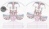
3 – The steering fins and actuators (AIM-9J)
In general, the steering mechanism of the AIM-9J is the same as the AIM-9B, but with an improved control system using a longer burning –bigger- gas generator (P019-28) for a 40 sec flight time, and more powerful actuators delivering 90 lb.ft torque to the canard. The canards (P018-29) were changed to the characteristic squared tip double delta platform, adopted to improve canard behaviour at higher angles of attack. Significant changes were made to the internal wiring harnesses.
An interesting difference between the AIM-9B and the AIM-9J is the placement of the pistons and the cylinder flange. With the AIM-9B the flange is placed directly below the electronics, the pistons pointing forward. With the AIM-9J the stainless steel cylinder flange (P019-30) is placed in the lower portion of the steering fins and actuator housing. The pistons (P019-31 point backward. The magnetically served bleeding valves (P019-32) are placed on the top side of the piston. The solenoid is made of red copper windings (P019-33), the bleeding hole (P019-34) is in the center.
6,700 of this subtype were eventually built or rebuilt from AIM-9Bs.
4 – The Warhead Mk.8 Mod.4 (Same for AIM-9B and AIM-9J) (P09)
The Warhead Mk.8 Mod.4 is a11,3 kg explosive (fragmentation) warhead containing 4,77 kg HBX-1 (mixture of 38% TNT, 40% hexogen, 17% aluminum and 5% potassium chloride as binding agent) (P09-35).
It is build up of a steel pipe (P09-36) with a wall thickness of 5 mm. A steel flange is brassed is top (P09-37). This flange houses a long sheet metal bushing (P09-38) which houses the Mk.304 impact fuze and Mk.35 booster, the short bushing in the base (P09-39) houses the Mk.34 booster of the proximity fuze.
A cardboard liner (P09-40) is glued to the inside of the wall of the warhead. This liner has a regular hole pattern allowing the explosive charge to contact the steel wall i.w.o. the holes, but keeping the explosive charge free from the steel wall of the warhead with the rest of the liner. This enshures an even pattern in the distribution of the –between- 1200 to 1500 fragments. These fragments are able to penetrate a steel plate of 10mm or a 25mm aluminum plate at a distance of 10 meters. The blast working is lethal for a plane up to 3 meters. The total mass of these patterned fragments is 2,6 kg, the top and base of the warhead have a different fragmentation pattern. The fragments have a speed of 2000 mtrs/sec, measured 2 meters from the point of detonation. Upon detonation, the fragments do not only move outward, but also forward with a 6 to 8 degree angle from the perpendicular on the centerline of the missile.
Both in top and base -on the inside-, a groove (P09-41) is machined to connect the warhead with the proximity fuze (P10) and the steering fin housing (P03) by means of four U shaped clamps at 90 degr. each that fixate the sections of the missile.
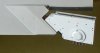
Although the Mk.304 impact fuze (P08) is screwed to the base of the steering fins and actuators section (P03), it is considered a part of the warhead Mk.8 Mod.4 warhead. In top of the fuze housing four prolonged plugs (P08-42) electrically connect the fuze to the electric power circuit of the missile. When the fuze is placed in the base of the steering fins and actuators section, a hexagonal collar nut fixates it into position (P08-43). The upper part of the fuze housing contains electronics like capacitators, resistances, and induction spools (P08-44).
The lower part houses the mechanical S & A (safety & arming) device (P08-45). This device exists of an electrically activated detonator, placed in a disc (P08-46). The detonator in the disc is rotated off line with the Mk.35 booster (P08-47). The disc is fixated in this position by a spring loaded set back weight (P08-48)which is forked over a small pin in the side of the disc, and slowed in it’s rotating movement –once released- by a small reduction gear (P08-49). This forms the firing safety, ensuring the missile will be armed before having travelled 250 mtrs from the launching point. Upon firing, the set back weight “falls backward”, releasing the disc to rotate. A clock spring will now rotate the disc so the firing cap is placed in line (centerline missile) with the Mk.35 booster, arming the fuze.
Upon direct impact with the target, the barium-trinitate crystals that are placed between the crossing points of the yokes of the canards are crushed when the canards are bend downward upon impact with the target. When crushed , the crystals deliver a 15 v current to the -already filled- impact fuze capacitor (P08-50), causing the capacitor to discharge over the electric detonator circuit of the fuze (P08-51), exploding the warhead.
The detonator in the disc contains appr. 1 gram of Lead azide. The Mk.35 booster contains 34 grams of Tetryl.
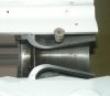
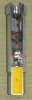
5 – The Mk.303 proximity fuze. (Same for AIM-9B and AIM-9J) (P10)
The Mk.303 proximity fuze is meant to explode the warhead of the missile when passing the target within 10 meters without impact.
The fuze housing exists of an aluminum pot (P10-52). It is threaded on the outside at the base, enabling it to be screwed in the top of the motor. In top it has a groove (P10-53) on the inside to connect it to the warhead by means of four U shaped clamps. On the inside the fuze is divided as follows; in the base the electronics are placed, cast in transparent resign (P10-54). In the center a big capacitor (P10-55) is placed to serve the four light emitters (P10-56). On top of this, a ring shaped cage (P10-57) with four pairs of light emitters (P10-56) and light receivers (P10-58) is placed along the inner circumference of the fuze housing. Four pairs of square holes are cut out in an even array i.w.o. these light emitters and receivers around the circumference of the fuze body. A transparent plastic strip is glued over these holes, forming the window (P10-59).
In the center of this array the mechanical S&A mechanism is placed (P10-60), including the electrical-mechanical self- destruct mechanism (P10-61). This device exists of an electrically activated detonator, placed in a rotating safety disc (P10-62). The detonator in the disc is rotated off line with the Mk.34 (P10-63) booster when unarmed. The disc is fixated in this position by a spring loaded set back weight (P10-64)over a small pin on the disc, and slowed in it’s rotating movement –once released- by a small reduction gear (on the backside). This forms the inertia firing safety, ensuring the missile will not be armed before having travelled 250 mtrs from the launching point. Upon firing, the inertia set back weight “falls backward”, releasing the disc to rotate. A clock spring will now rotate the disc so the firing cap in the disc is placed in line (centerline missile) with the Mk.34 booster –closing an electric circuit as well-, arming the fuze.
The detonator in the disc contains appr. 1 gram of Lead azide. The Mk34 booster contains 35 grams of Tetryl.
The four light emitters send out light in a radial pattern, each covering 90 degrees of radius around the missile. If this light is bounced back to the receiver by an object that passes the missile within 10 meters of the missile, the electric resistance of the light sensitive resistance in the receiver will fall, enabling to pass an electric current to the electric detonator of the proximity fuze. Of course the wavelength of the light is chosen in such a way that this light does not appear naturally, and the receiver will react only on this type of wavelength.
Attachments
-
 P01 - AIM-9B sidewinder cutaway model.JPG77.9 KB · Views: 121
 -
 P02 - AIM-9B Sidewinder forward section cutaway model.jpg95.5 KB · Views: 121
 -
 P03 - AIM-9B sidewinder missile seeker and steering gear.jpg94.9 KB · Views: 118
 -
 P04 - AIM-9B Infra red reticle seeker explained.jpg98.7 KB · Views: 118
 -
 P05 - AIM-9B Sidewinder amplidude modulation ,.jpg86.4 KB · Views: 101
 -
 P06 - AIM-9B Sidewinder missile block diagram.jpg97.5 KB · Views: 90
 -
 P07 - AIM-9B Sidewinder Turbine generator.jpg97.7 KB · Views: 105
 -
 P08 - AIM-9 Sidewinder Mk.304 impact fuze with Mk.35 booster 2.jpg88.2 KB · Views: 99
Last edited: