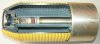
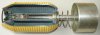
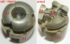
Cutaway model of a BLU-49/B anti personel fragmentation bomblet. The body of the bomb is prefragmentated and has a machined hole in nose and base to receive a thin steel bushing that runs through the bomb body. In the wide top part of this bushing the impact fuze is placed, the telescoped tail is placed in the smaller diameter afterward part of the bushing. In transport, the springloaded tail is kept in inward position by a mechanisn, existing of six air tabs, a retainer band an a wind tab. Upon release of the bomb from the dispenser the wind tab rotates, releasing the retainer band and the air tabs, enabeling the tail to move outward, forming the aerodynamic stabilizer.
The BLU-49/B was designed to penetate jungle foilage and detonate on ground impact. The main difference between the BLU49/B and the BLU-49A/B was that the BLU-49A/B had a slightly different nose with a foil covering instead of a protruding shipping pin. The shipping pin is connected to the telescope pipe of the tail and –with the tail in forward (safe) position- keeps the fuze in a safe position , unable to arm untill the tail has fully extended. The fuze is fixated in the fuze well by means of a circlip.
Two other types of BLU-49 bomblets were the BLU-49B/B, which has a pyroforic liner for an additional incendiary effect and the BLU- 87/B, which has a detonation delay of 0,015seconds.
The BLU-49/B was used in the following cluster bombs / dispensers:
CBU-38/A, 40 pcs of BLU-49/B in the SUU-13/A
CBU-81/A, 45 pcs of BLU-49/B in an unknown type dispenser.
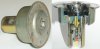
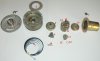
List of fuze parts:
1 - Upper fuze body
2 - Speed reduction gear box
3 - Nosecap
4 - Cup for springloaded striker pin
5 - Springloaded striker pin
6 - Lock up ring
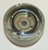
7 - Clock spring
8 - Arming wheel (painted blue)
9 - Arming key (painted yellow in cutaway)
10- Connecting pin (painted green in vutaway model)
11- Housing for inertia ring segments, firing pin and rotation shutter
12- Inertia ring segments (3)
13- Rotation shutter with firing cap (F)
14- Rotation spring for rotation shutter
15- fixation leafspring
16- Detonator (housing)
17- Lower part of fuze body
18- Firing pin (springloaded)
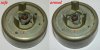
Functioning of the fuze:
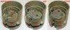
Shortly after release of the bomblet, the tail extends and the shipping pin is retracted. The arming wheel (8) is released and the clockspring (7) will start to rotate the arming wheel. The arming wheel has a toothgear on the outside, which grips in a speed reduction gear box (2). This enshures the bomblet is not armed in the vincinity of the aircraft which released it. The lower side of the arming wheel (8) has a Y shaped indentation, in which a Y shaped “key” fits that is formed by the lower part of the arming key (9). In safe (lower) position the arming key keeps the three inertia ring segments (12) locked tight in inward position. These inertia weights keep –in inward position- the springloaded firingpin (18) in downward position. The firingpin –in downward position- keeps the rotation shutter (13) with the firing cap in a locked position, out of line with the detonator (16).
When the arming wheel (8) has rotated approximately 60 degrees, the Y shaped key of the arming key (9) fits into the Y shaped indentation, thereby moving upward, releasing the three inertia ring segments (12) to move in an outward position, forced by the firing pin (spring) (8) moving upward. The rising firing pin releases the rotation shutter (13) which will rotate the firing cap (F) between the firing pin and the detonator (16). The fuze is now fully armed.
There are two ways to activate the firing pin:
- Hydraulic / pneumatic : In the nosecap (3) of the fuze four holes are drilled. To the underside of this nosecap a cup (4) is spotwelded in which a springloaded striker pin (5) is placed. A connecting pin (10) is placed in a hole drilled through the center of the arming key (9). Upon impact on water, mud or swamp, the striker pin (5) will be hit back by the hydraulic / pneumatic force, pushing the connecting pin (10) backward, so forcing the firing pin (8) into the firing cap (F). This will ignite the detonator, booster and main charge.
- Inertia. If the bomblet hits thick jungle foilage and branches this may decrease the speed of the bomb so much that the hydraulic / pneumatic fuze may not function propperly . Therefore an inertia fuze is build in. If a hard object is hit, or a sudden continuous desceleration is reached, the inertia ring segments (12) are thrown forward, pivoting around their hinge pins. As a results of this rotating movement, the pins connected to these weights will push the firing pin (8) into the firing cap (F), exploding the bomb. In fact a straight forward movement (inertia ring segments) is reversed into a straigt movement backward (firing pin). The fuze will also function if the bomb hits an object under an angle.
Data for BLU-49/B:
Length: 34.3 cm (13.5 in) with extende tail
Diameter: 11.7 cm (4.6 in)
Weight: 6.4 kg (14.1 lb)
Explosive: 2.1 kg (4.6 lb) Cyclotol
Regards, DJH
The BLU-49/B was designed to penetate jungle foilage and detonate on ground impact. The main difference between the BLU49/B and the BLU-49A/B was that the BLU-49A/B had a slightly different nose with a foil covering instead of a protruding shipping pin. The shipping pin is connected to the telescope pipe of the tail and –with the tail in forward (safe) position- keeps the fuze in a safe position , unable to arm untill the tail has fully extended. The fuze is fixated in the fuze well by means of a circlip.
Two other types of BLU-49 bomblets were the BLU-49B/B, which has a pyroforic liner for an additional incendiary effect and the BLU- 87/B, which has a detonation delay of 0,015seconds.
The BLU-49/B was used in the following cluster bombs / dispensers:
CBU-38/A, 40 pcs of BLU-49/B in the SUU-13/A
CBU-81/A, 45 pcs of BLU-49/B in an unknown type dispenser.
List of fuze parts:
1 - Upper fuze body
2 - Speed reduction gear box
3 - Nosecap
4 - Cup for springloaded striker pin
5 - Springloaded striker pin
6 - Lock up ring
7 - Clock spring
8 - Arming wheel (painted blue)
9 - Arming key (painted yellow in cutaway)
10- Connecting pin (painted green in vutaway model)
11- Housing for inertia ring segments, firing pin and rotation shutter
12- Inertia ring segments (3)
13- Rotation shutter with firing cap (F)
14- Rotation spring for rotation shutter
15- fixation leafspring
16- Detonator (housing)
17- Lower part of fuze body
18- Firing pin (springloaded)
Functioning of the fuze:
Shortly after release of the bomblet, the tail extends and the shipping pin is retracted. The arming wheel (8) is released and the clockspring (7) will start to rotate the arming wheel. The arming wheel has a toothgear on the outside, which grips in a speed reduction gear box (2). This enshures the bomblet is not armed in the vincinity of the aircraft which released it. The lower side of the arming wheel (8) has a Y shaped indentation, in which a Y shaped “key” fits that is formed by the lower part of the arming key (9). In safe (lower) position the arming key keeps the three inertia ring segments (12) locked tight in inward position. These inertia weights keep –in inward position- the springloaded firingpin (18) in downward position. The firingpin –in downward position- keeps the rotation shutter (13) with the firing cap in a locked position, out of line with the detonator (16).
When the arming wheel (8) has rotated approximately 60 degrees, the Y shaped key of the arming key (9) fits into the Y shaped indentation, thereby moving upward, releasing the three inertia ring segments (12) to move in an outward position, forced by the firing pin (spring) (8) moving upward. The rising firing pin releases the rotation shutter (13) which will rotate the firing cap (F) between the firing pin and the detonator (16). The fuze is now fully armed.
There are two ways to activate the firing pin:
- Hydraulic / pneumatic : In the nosecap (3) of the fuze four holes are drilled. To the underside of this nosecap a cup (4) is spotwelded in which a springloaded striker pin (5) is placed. A connecting pin (10) is placed in a hole drilled through the center of the arming key (9). Upon impact on water, mud or swamp, the striker pin (5) will be hit back by the hydraulic / pneumatic force, pushing the connecting pin (10) backward, so forcing the firing pin (8) into the firing cap (F). This will ignite the detonator, booster and main charge.
- Inertia. If the bomblet hits thick jungle foilage and branches this may decrease the speed of the bomb so much that the hydraulic / pneumatic fuze may not function propperly . Therefore an inertia fuze is build in. If a hard object is hit, or a sudden continuous desceleration is reached, the inertia ring segments (12) are thrown forward, pivoting around their hinge pins. As a results of this rotating movement, the pins connected to these weights will push the firing pin (8) into the firing cap (F), exploding the bomb. In fact a straight forward movement (inertia ring segments) is reversed into a straigt movement backward (firing pin). The fuze will also function if the bomb hits an object under an angle.
Data for BLU-49/B:
Length: 34.3 cm (13.5 in) with extende tail
Diameter: 11.7 cm (4.6 in)
Weight: 6.4 kg (14.1 lb)
Explosive: 2.1 kg (4.6 lb) Cyclotol
Regards, DJH
Attachments
-
 Cutaway BLU-49B Safe, tail inward.jpg96.1 KB · Views: 141
 -
 Cutaway BLU-49B armed, tail extended.jpg100.3 KB · Views: 124
 -
 Fuze BLU-49B.JPG85.8 KB · Views: 107
 -
 Fuze BLU-49B taken apart.jpg91.2 KB · Views: 91
 -
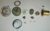 Fuze BLU-49B taken apart other side.jpg93.3 KB · Views: 80
 -
 Arming key (9) in safe and armed position.jpg95.8 KB · Views: 78
 -
 clockspring (7) around arming wheel (8).JPG77.7 KB · Views: 74
 -
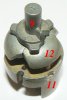 Inertia ring segments (12) in inward position with arming key (9) on top.JPG58.8 KB · Views: 79
 -
 Inertia ring segments (12) safe-impact-armed.JPG67.6 KB · Views: 83
 -
 rotation shutter (13) safe and armed.jpg97 KB · Views: 75
Last edited: