What's new
British Ordnance Collectors Network

This is a sample guest message. Register a free account today to become a member! Once signed in, you'll be able to participate on this site by adding your own topics and posts, as well as connect with other members through your own private inbox!

Can someone explain German Electrical condensor fuzes to me please?

pointblank0

BOCN Supporter
Hello everyone.

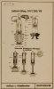
I am finding it very difficult finding BASIC information on these German bomb fuzes. Everything I look at seems to assume that you are quite up on the old electronics and stuff! So this is what I want to know. I am niot after info on the clockwork parts or anti handling devices etc, just the electronic bits such as the 15 and 25.

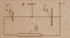
How is the initaial charge put into the fuzes? I have read that they were charged via a cap and lead as the bombs left the plane, but would this be a massive charge blast into the resistors that then trickle down into the capacitors? How long did it take for the initial charge to go through? What keeps the circuit open to allow the current to flow through the resistors and into the capasitors? How does this work exactly?

Sorry for all these questions, but electronics is something I struggle getting my head around. Can someone explain this to me as if I were a small child, preferebly with a few diagrams?

Thanks everyone.
 
There is a basic explanation on here but perhaps not as detailed as you are looking for.

http://www.bombdisposalclub.org.uk/BD_history.htm

I can tell you the electrical fuzes were only armed when the bombs were released, this was a safety mechanism so that until the bombs were released they were 'safe'. As to the actual circuitry will leave that to someone else.

regards Kev
 
Basically in the plane there is a cap that fits onto the top of the fuse head with 2 contacts or one contact on either the side of the fuse head some times it uses the body of the fuse to make the other contact, not going in to much detail here.
when the bomb is released from the plane the capacitors are charged and the fuse is armed, when the bomb hits the ground there is a small spring that closes the contact and kaboom or starts a delay, many different variations.
pictures of springs,,,,,,,, Dave

HPIM0083.jpgHPIM0084.jpgHPIM0085.jpgHPIM0080.jpgHPIM0081.jpgHPIM0082.jpg
 
Thanks for your help. pzgr40's explanation is fantastic. I take it that the glow tube doesn't connect till the trembler switch is initiated?
 
Thanks for your help. pzgr40's explanation is fantastic. I take it that the glow tube doesn't connect till the trembler switch is initiated?
You got something very wrong there. "Glowtubes" are used in timefuzes only, like in flarebombs and photographic flash-bombs. Bombs that are supposed to hit the ground use "springs" as switches to close a circuit. If a more detailed explanation of "Rheinmetall" electric fuzes is needed, please feel free to ask and I will sit down to write one.
Regards,
Bellifortis.

Very large subject, i tried to just give a small explanation on basic No25 some are so complicated i struggle to understand them and im a auto electrician / refrigeration electrician but thats why i collect,,,,,,,, Dave
 
Very large subject, i tried to just give a small explanation on basic No25 some are so complicated i struggle to understand them and im a auto electrician / refrigeration electrician but thats why i collect,,,,,,,, Dave
Hi Dave,
15 years ago I had about lost interest in the "Rheinmetall" fuzes. They all looked the same and I did not understand the differences. But, it's all quite easy, 80 years old electrotechnics. They all are basically an "RC delay circuit", as the americans say. In the instant of release of the bomb the STORAGE-condenser in the fuze is charged with electricity from the planes battery. While falling, electricity leaks from the storage-condenser through one or more RESISTORS to the FIRING-condenser. So it takes some time before the fuze is fully armed. Upon impact, if release of the bomb was high enough and the fuze now fully armed, a TREMBLER-switch closes the circuit of the firingcondenser and an electric match. That's basically all. One exeption is the (9) timefuze with the glow-tube. This is quite well explained in Pzgr40 above mentioned post. If more details like the workings of the "Zuenderschaltkasten" and the "Schloss" (charginggear) are wanted, ask.
Greetings,
Bellifortis.
 
You got something very wrong there. "Glowtubes" are used in timefuzes only, like in flarebombs and photographic flash-bombs. Bombs that are supposed to hit the ground use "springs" as switches to close a circuit. If a more detailed explanation of "Rheinmetall" electric fuzes is needed, please feel free to ask and I will sit down to write one.
Regards,
Bellifortis.

Thanks for your reply. Yes, I would love a detailed explanation if you could. The part I am struggling with is the initial charging and equipment involved, and the circuit after the plug has been released and what stops the curent leaking till time of detenation.

Many thanks
 
Last edited:
Hi Dave,
15 years ago I had about lost interest in the "Rheinmetall" fuzes. They all looked the same and I did not understand the differences. But, it's all quite easy, 80 years old electrotechnics. They all are basically an "RC delay circuit", as the americans say. In the instant of release of the bomb the STORAGE-condenser in the fuze is charged with electricity from the planes battery. While falling, electricity leaks from the storage-condenser through one or more RESISTORS to the FIRING-condenser. So it takes some time before the fuze is fully armed. Upon impact, if release of the bomb was high enough and the fuze now fully armed, a TREMBLER-switch closes the circuit of the firingcondenser and an electric match. That's basically all. One exeption is the (9) timefuze with the glow-tube. This is quite well explained in Pzgr40 above mentioned post. If more details like the workings of the "Zuenderschaltkasten" and the "Schloss" (charginggear) are wanted, ask.
Greetings,
Bellifortis.

this explains a lot. But, how long does it take to charge the initial condensors prior to leaving the plane? If a bomb was dropped too low for the fuze to have enough power in the firing condensor, would this then become a sitting booby trap? Would it be a case of having a dropped bomb, electronic initiated fuze that hasn't had enough power to detonate at the time of impact, but the condensors have leaked enough since landing to make any movement of the bomb delicate and prone to detonation?
 
I think capacitor is the actual right word?

As an example the El.A.Z.25 had 3 - 10,5 sec. arming time. It was possible to regulate the arming time from inside the aircraft prior to dropping. The arming time was regulated depending from the dropping altitude and speed of the dropping aircraft by adjusting the charging voltage (150-240 V). The arming time should protect the aircraft. If the bomb was dropped at to low altitude it should NOT explode to prevent damages on the aircraft. For deep flying aircraft the El.A.Z.25 could be set to explode after a 14 sec. delay. If the delay setting was chosen the arming time was only 0,4-0,8 sec.

Yes, if the bomb impacted prior to reaching the arming time it became some sort of a heavy booby trap. But as the voltage inside the foil capacitors is disappearing continuously (leakage current) the voltage should go down below a safe level within some hours or a few days.
 
Last edited:
Hallo,
Alpini has already answered some questions. I will split my answer into a few posts, so my rantings won't be too long. The basic problem 80 years ago was, to produce capacitors (thank you alpini ) small enough and bridgewires thin enough. The electric igniter heads used were much, much more sensitive than any used today, they only needed 500 ergs. The average igniting energy at 30 V and o,35 microfarad = 0,2 mWs = 160 microJoule. The SX6 igniter used a Nicrom bridgewire of 12000 Ohm / m. This is so thin that it can only be handled under oil. I attach some pictures 1.: The dropping time schematic of a (55)fuze 2.: dropping time schematic of a (25)fuze 3.: electricity flow schematic in a (25)fuze 4.: Construction drawing of a (25) fuze 5.: Charging Gear EHVC 500/8 as an example. There are many other models. This is the gear that attaches to the fuzehead under the plane. On release of the bomb, the charging head stays attached for a few cm drop until it slips off the fuze head. This very short moment is the electrical charging time. The storage capacitor is now filled, but the firing capacitor is still empty and the fuze can not ignite, even if some switch should close. The 2 charging plungers of the fuze have an insulated surface in their lower third and are held in position by a spring under them. In this (transport) position the circuit is open. The pins of the charging head depress the plungers and close the circuit. On release the plungers are pressed back in the transport position.
 

Attachments

  • Rheinmetall 412.jpg
    Rheinmetall 412.jpg
    275.7 KB · Views: 48
  • Rheinmetall 431.jpg
    Rheinmetall 431.jpg
    282.6 KB · Views: 46
  • Rheinmetall 434.jpg
    Rheinmetall 434.jpg
    281.1 KB · Views: 48
  • Rheinmetall 435.jpg
    Rheinmetall 435.jpg
    281.9 KB · Views: 48
  • Rheinmetall 396.jpg
    Rheinmetall 396.jpg
    277.7 KB · Views: 49
The first picture is a diagram of the (25 C)fuze. Here you can see that this fuze has 4 igniter circuits, normal is 3. One "Instantaneous", second "Short Delay" and the third "Long Delay" marked in german "VZ"= Verzugszuendung. This is a 14 sec. pyrotechnic delay tube seen in the middle. The second picture is of an early model "Zuenderschaltkasten"= fuze-switching-box, ZSK 242. This box is situated in front, to right of the pilot. Up till just before release of the bomb, the pilot could decide on arming time and delay (within limits) by switching on higher or lower arming voltage. When choosing lower voltage (150-180 V) arming time of the fuze would be longer, when choosing the high 240 V, arming time would be shorter. The VZ-circuit is always the first to be armed, so if the bomb is dropped very low it is detonated by the 14 Sec. long delay circuit, to leave the plane more than enough time to get out of the danger zone. The other circuits won't have time enough to aRühlemann 118.jpgZSK 242.jpgrm. This you can see in the first 2 pictures of my last post.
P.S.: The foto of the ZSK 242 is not my own, but gleaned from the world wide web.
 
Last edited:
Thanks everyone, starting to get my head around these now I think.

I always thought that the term condenser was an old term for a capacitor in electronics. I take it I am wrong with this assumption?
 
Martin,

In this context, what does Ein & Aus translate to?

PB - Condensor was the old name for capacitor.

TimG

Couple of images of a telescopic charging head.


French de miners book 005.jpgFrench de miners book 007.jpg
 
Hi Tim,
Ein and Aus simply mean On and Off. To make shure that no charge can be supplied to the fuze during flight by accident., the ZSK is always in the OFF position. Only when the plane is above the target, the ZSK is switched to ON
Martin,

In this context, what does Ein & Aus translate to?

PB - Condensor was the old name for capacitor.

TimG

Couple of images of a telescopic charging head.


View attachment 96184View attachment 96185
 
this explains a lot. But, how long does it take to charge the initial condensors prior to leaving the plane? If a bomb was dropped too low for the fuze to have enough power in the firing condensor, would this then become a sitting booby trap? Would it be a case of having a dropped bomb, electronic initiated fuze that hasn't had enough power to detonate at the time of impact, but the condensors have leaked enough since landing to make any movement of the bomb delicate and prone to detonation?
Also alpini has already given some answers, I will add a little. As explained before, the foil-condensers of the 1930s were not able to store much electricity. So very little energy was available and the electric igniter fuseheads had to be made extremely sensitive. With 3 or even 4 circuits in a fuze, there were 6-8 condensers rolled up one on the other. this looks like 1 big condenser roll. The firing condenser is always smaller than the storage condenser. This means, that such a small foil-condenser-roll will also loose its charge more fast. So, a bomb that was dropped so low (20m), that none of the circuits had enough time to charge would become armed after it has settled but also start loosing electricity by seepage. After a certain time the condensers would have lost all their charge. Most bombfuzes needed 50 times the force of gravity as constant acceleration for the fuzetremblerswitch to close a circuit. The (50) is an exeption, it only needed 1/3 the force of gravity, but this was manufactured as a booby-trap to safeguard it from manipulation.
Bellifortis.
 
Here now a basic drawing, by the inventor himself, explaining the "Umladeschaltung"(help,I can't translate this word). C3 is the storage capacitor and C4 the firing capacitor. I should have posted this at the beginning, but only thought of it now.
Bellifortis
 

Attachments

  • IMG_0085.JPG
    IMG_0085.JPG
    290.9 KB · Views: 32
Top