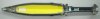
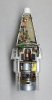
Cutaway model of a 120 mm high explosive mortar shell as used in the “Mortar -120-RT”. RT stands for Raye, Tracte, which means rifled, towed. The weapon was designed by French Thomson-Brandt company.
The Projectile described in this posting is the Dutch manufactured CTG NR 104 for this mortar, manufactured by the AI (Artillerie Inrichting, Zaandam), a factory that does not exist anymore.
The mortar shell has some very interesting design features that make it quite unique.
For a starter: as the mortar is rifled, it is spin stabilized and therefore uses a normal artillery fuze, either the PD M577 impact fuze , either the proximity fuze VT169 or VT169K
The projectile body has the normal artillery shell shape.
The tail is being thrown off upon leaving the barrel, and is projected away from the weapon by a small rocket motor in the tail.
The body of the mortar projectile is made of thin walled cast iron, screwed to a steel base plate. The fuze M577 is screwed in the Booster M125A1. This combination is screwed in top of the projectile body.
The projectile has a pre rifled drivingbelt.
A secondary transparent plastic driving belt is placed around the lower portion of the shell body, below the pre rifled driving belt. Upon firing it is pushed upward into the lands and grooves to form a gastight sealing, preventing gas from leaking away between the pre rifled drivingbelt and the lands and grooves.
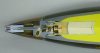
Description of the fuze M577:
The fuze is screwed into the Booster M125A1
The fuze has a nose part with a –direct action- percussion primer, at which the firing pin is kept away from the detonator below it by a small brass bushing. This top part is screwed upon a small threaded pipe which is screwed into the main fuze body. A radial set screw in the fuze body can be rotated 90 degrees to open either lock off this channel.
Inside the fuze body, a concussion fuze is placed with a delayed detonator that moves forward into a firing pin upon impact or graze. The flame of either of these two detonators is projected downward into the booster M125A1, which changes the flame which appears from the centre hole in the base of the fuze into a detonation in the rotation shutter of the M125A1 booster. The detonation is this shutter ignites the main booster charge of the M125 A1 booster-screwed to the base of the booster-, which ignites the main charge in the shell body. The safety mechanism in the M125A1 booster is a rotating shutter, delayed in rotation by a gear train. This ensures the booster arms only after leaving the barrel of the weapon.
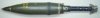
The base plate of the shell body has a ring with a rim machined on its side, over which the tail is mounted, held in position with three steel spring clamp strips, screwed to the tail. The tail houses the ignition charge. Over the tail horseshoe shaped extra charges can be added to increase the range of the projectile. The tail has two cast aluminium guide pieces (top and bottom) mounted that have three notches; these are meant to guide the tail on its way out of the barrel. The lower part of the upper guide piece forms a gas chamber with four radial holes that fill with propulsion gasses upon firing. Below the upper guide piece, a steel pocket motor is screwed, with a small propulsion charge (green). Two venturi’s (red) are placed 180 degrees opposite.
The lower guidance piece houses a firing pin that ignites the propelling cartridge. The hole in the base fits over a protruding shaft in the base of the weapon with a close tolerance fit.
The propelling cartridge has a sheet brass base, and a cardboard body. A small perforated pipe is placed in the centre of the cartridge, filled with fine powder at the base and in top. This is meant to ignite the main charge of this cartridge instantaneously.
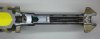
Functioning of the tail:
The mortar shell is dropped in the barrel, after rotating it slightly to let the rotating band enter the lands and grooves. When it falls to the bottom of the tube of the weapon there are two possibilities: the firing pin of the weapon is placed in upward position, so the firing pin in the tail is activated at once and the shell is fired, either the firing pin of the weapon has to be activated with a lanyard to hit the firing pin in the base of the tail of the shell.
The propulsion cartridge is ignited, on its turn igniting the augmental charges (not in this picture) pushing the shell out of the barrel. The close tolerance fit of the lower cast piece (suction) over the protruding shaft -of the weapon- together with the rapidly rising pressure in the gas chamber of the upper guide piece release the projectile from the tail by ripping it loose from the three spring metal clamp strips. At the same time the fuel stick of the rocket motor (green) is ignited through the venturi holes (red) propelling the tail out of the barrel. It will end approximately 70 mtrs. in front of the weapon, safely away from the crew serving the weapon.
Two you tube movies showing the weapon and the shells in action can be found here:
https://www.youtube.com/watch?v=w5F8N-KoldI
https://www.youtube.com/watch?v=y-EzoOP1vlM
It can clearly be observed how the tail is thrown out separated from the shell.
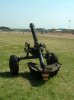
The Mortar -120-RT is used by the following countries:
Azerbaijan, Belgium, Brazil, Colombia, Cyprus, Djibouti, France ,India, Israel, Italy, Japan, Jordan, Netherlands, Saudi Arabia, Tunesia, Turkey, USA.
Length of complete shell : 897mm
Length of shell body : 580mm
Length of tail : 335mm
Weight of complete shell : 18,8 kg
Weight of projectile : 15,7 kg
Weight of explosive charge : 3,9 kg
Weight of propulsion cartridge : 0,195 kg.
Minimum range / Vo : 1269 mtrs @ 115 mtrs/sec (no extra add on charges)
Maximum range / Vo : 8135 mtrs @ 365 mtrs/sec (Charge 10)
Regards, DJH
The Projectile described in this posting is the Dutch manufactured CTG NR 104 for this mortar, manufactured by the AI (Artillerie Inrichting, Zaandam), a factory that does not exist anymore.
The mortar shell has some very interesting design features that make it quite unique.
For a starter: as the mortar is rifled, it is spin stabilized and therefore uses a normal artillery fuze, either the PD M577 impact fuze , either the proximity fuze VT169 or VT169K
The projectile body has the normal artillery shell shape.
The tail is being thrown off upon leaving the barrel, and is projected away from the weapon by a small rocket motor in the tail.
The body of the mortar projectile is made of thin walled cast iron, screwed to a steel base plate. The fuze M577 is screwed in the Booster M125A1. This combination is screwed in top of the projectile body.
The projectile has a pre rifled drivingbelt.
A secondary transparent plastic driving belt is placed around the lower portion of the shell body, below the pre rifled driving belt. Upon firing it is pushed upward into the lands and grooves to form a gastight sealing, preventing gas from leaking away between the pre rifled drivingbelt and the lands and grooves.
Description of the fuze M577:
The fuze is screwed into the Booster M125A1
The fuze has a nose part with a –direct action- percussion primer, at which the firing pin is kept away from the detonator below it by a small brass bushing. This top part is screwed upon a small threaded pipe which is screwed into the main fuze body. A radial set screw in the fuze body can be rotated 90 degrees to open either lock off this channel.
Inside the fuze body, a concussion fuze is placed with a delayed detonator that moves forward into a firing pin upon impact or graze. The flame of either of these two detonators is projected downward into the booster M125A1, which changes the flame which appears from the centre hole in the base of the fuze into a detonation in the rotation shutter of the M125A1 booster. The detonation is this shutter ignites the main booster charge of the M125 A1 booster-screwed to the base of the booster-, which ignites the main charge in the shell body. The safety mechanism in the M125A1 booster is a rotating shutter, delayed in rotation by a gear train. This ensures the booster arms only after leaving the barrel of the weapon.
The base plate of the shell body has a ring with a rim machined on its side, over which the tail is mounted, held in position with three steel spring clamp strips, screwed to the tail. The tail houses the ignition charge. Over the tail horseshoe shaped extra charges can be added to increase the range of the projectile. The tail has two cast aluminium guide pieces (top and bottom) mounted that have three notches; these are meant to guide the tail on its way out of the barrel. The lower part of the upper guide piece forms a gas chamber with four radial holes that fill with propulsion gasses upon firing. Below the upper guide piece, a steel pocket motor is screwed, with a small propulsion charge (green). Two venturi’s (red) are placed 180 degrees opposite.
The lower guidance piece houses a firing pin that ignites the propelling cartridge. The hole in the base fits over a protruding shaft in the base of the weapon with a close tolerance fit.
The propelling cartridge has a sheet brass base, and a cardboard body. A small perforated pipe is placed in the centre of the cartridge, filled with fine powder at the base and in top. This is meant to ignite the main charge of this cartridge instantaneously.
Functioning of the tail:
The mortar shell is dropped in the barrel, after rotating it slightly to let the rotating band enter the lands and grooves. When it falls to the bottom of the tube of the weapon there are two possibilities: the firing pin of the weapon is placed in upward position, so the firing pin in the tail is activated at once and the shell is fired, either the firing pin of the weapon has to be activated with a lanyard to hit the firing pin in the base of the tail of the shell.
The propulsion cartridge is ignited, on its turn igniting the augmental charges (not in this picture) pushing the shell out of the barrel. The close tolerance fit of the lower cast piece (suction) over the protruding shaft -of the weapon- together with the rapidly rising pressure in the gas chamber of the upper guide piece release the projectile from the tail by ripping it loose from the three spring metal clamp strips. At the same time the fuel stick of the rocket motor (green) is ignited through the venturi holes (red) propelling the tail out of the barrel. It will end approximately 70 mtrs. in front of the weapon, safely away from the crew serving the weapon.
Two you tube movies showing the weapon and the shells in action can be found here:
https://www.youtube.com/watch?v=w5F8N-KoldI
https://www.youtube.com/watch?v=y-EzoOP1vlM
It can clearly be observed how the tail is thrown out separated from the shell.
The Mortar -120-RT is used by the following countries:
Azerbaijan, Belgium, Brazil, Colombia, Cyprus, Djibouti, France ,India, Israel, Italy, Japan, Jordan, Netherlands, Saudi Arabia, Tunesia, Turkey, USA.
Length of complete shell : 897mm
Length of shell body : 580mm
Length of tail : 335mm
Weight of complete shell : 18,8 kg
Weight of projectile : 15,7 kg
Weight of explosive charge : 3,9 kg
Weight of propulsion cartridge : 0,195 kg.
Minimum range / Vo : 1269 mtrs @ 115 mtrs/sec (no extra add on charges)
Maximum range / Vo : 8135 mtrs @ 365 mtrs/sec (Charge 10)
Regards, DJH
Attachments
-
 01 - 12cm Ctg Nr104 HE mortier cutaway.JPG77 KB · Views: 44
 -
 02 - 12cm Ctg Nr104 HE mortier backside.JPG67.1 KB · Views: 35
 -
 03 - 12cm Ctg Nr104 HE mortier fuze M577.JPG60.2 KB · Views: 34
 -
 04 - 12cm Ctg Nr104 HE mortier tail.JPG189.3 KB · Views: 29
 -
 05 - Proximity fuze Nr 169.jpg238.3 KB · Views: 33
 -
 06 - Mortier -120-RT.jpg85.3 KB · Views: 19
Last edited: