What's new
British Ordnance Collectors Network

This is a sample guest message. Register a free account today to become a member! Once signed in, you'll be able to participate on this site by adding your own topics and posts, as well as connect with other members through your own private inbox!

Fuze cap production using deep drawing

Alpini

Well-Known Member
Premium Member
Hello,

I wan't to show another long-time restoration project which I just finished. Since some years I had an experimental mechanical time fuze which is much comparable to a German "Dopp. Z. 16" fuze but it was missing it's steel cap. Some months ago I got a second one which is basically the same but without a percussion system. This one is much comparable to a "Dopp. Z. 16. o. A.Z.". The clockwork of both fuzes seems to be the same as in the Dopp. Z. 16 but the Dopp. Z. 16 has an additional set-back ring which prevents a rotation of the fuze (setting-)cap when it is fired. I think my experimental models are made after the Dopp.Z.16 fuzes because it shares more construction details with later Zt.Z.S/30 fuzes than with the Dopp.Z.16 series.

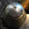
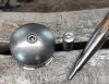
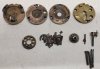
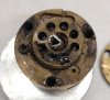
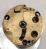
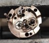
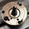
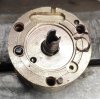
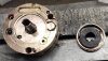
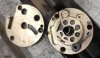
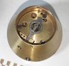
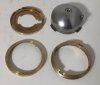
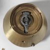
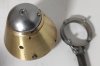
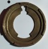
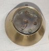
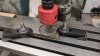
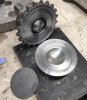
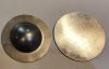
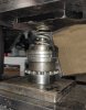
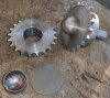
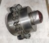
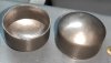
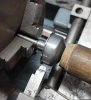
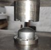
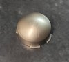
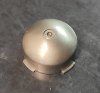
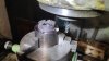
First of all I upload two pictures. One is showing the fuze with it's clockwork and the seat for the cap. And the second picture shows a small brass ring which originally was connected to the fuze cap. Both the brass ring + the cap were used to set the time of ignition.
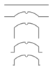
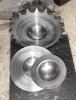
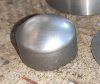
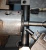
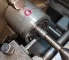
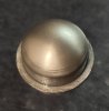
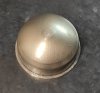
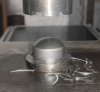
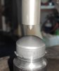
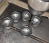
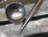
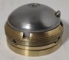
 

Attachments

  • 02.jpg
    02.jpg
    139.7 KB · Views: 14
  • 01.jpg
    01.jpg
    226.2 KB · Views: 16
Some years ago I already made one of the needed caps using the metal spinning process but later noticed that the shape of the cap was not perfect as it was some Millimeters to short and it had a wrong radius so I wanted to make two new caps. Initially I wanted to make the radius of the cap using my hydraulic press and the following steps using metal spinning. The pictures show:

-the planned manufacture-steps using metal spinning
-cutting the metal disc using a circular hole saw
-the first production step done on the press with the used tools (2 pictures)
-the workpiece at the early stage together with a blank metal disc used
-the tool under the hydraulic press with strong springs used to hold down the pressure pad to prevent folds

For manufacturing the tools I used old gears which were scrapped at my work many years ago.
 

Attachments

  • 03.png
    03.png
    30.8 KB · Views: 25
  • 04.jpg
    04.jpg
    77.9 KB · Views: 28
  • 04b.jpg
    04b.jpg
    140.6 KB · Views: 31
  • 05.jpg
    05.jpg
    165 KB · Views: 30
  • 06.jpg
    06.jpg
    290.3 KB · Views: 31
  • 08.jpg
    08.jpg
    115.6 KB · Views: 32
Last edited:
After this first step I noticed that the diameter of the blank reduced from 58 mm to 53 mm and I though hmmm, that's already nearly a deep drawn workpiece so why not try to deep draw it completely. But I also tough that it won't be successful in a home workshop with non hardened tools used and probably my hydraulic press having much to less power. The only thing to alter was the lower die. Instead of having a radius the new lower die has just a hole in it with the upper edge where the material is flowing inside slightly rounded.

For the first test I still used two strong springs to hold down the pressure pad. To my surprise it worked relatively well with just slight folds appearing on the lower end of the cap:
 

Attachments

  • 07.jpg
    07.jpg
    107 KB · Views: 20
  • 09.jpg
    09.jpg
    83.7 KB · Views: 19
To prevent the folds I was searching for a stronger spring but without success but then I had the idea to screw the pressure pad to the lower die and this was a good solution. Now just the second test went perfectly: no more folds and the dimensions fit perfect into the fuze. My fear the the press is to weak was very wrong. It has a max. pressure of 200 bar but the manometer only went to 40 bar shortly. The calculated force required to deep draw the cap at 40 bar was just about 50 kN or 5 tons.
 

Attachments

  • 08a.jpg
    08a.jpg
    70.5 KB · Views: 16
  • 10.jpg
    10.jpg
    72.2 KB · Views: 20
  • 10a.jpg
    10a.jpg
    165.2 KB · Views: 18
Last edited:
The next step was to add a rim to the deep drawn cap. For this I used the metal spinning process on the lathe with a 6 mm tungsten rod (part of a broken endmill) as the tool lubricated with oil and as a last step I turned this rim to the needed diameter. Not much more to say about these small steps.

I'll continue the thread this evening with one more punching step to cut out segments of the rim, an embossing step and lastly riveting a small steel pin which was required for the fuze setting tool.
 

Attachments

  • 11.jpg
    11.jpg
    82 KB · Views: 20
  • 12.jpg
    12.jpg
    69.1 KB · Views: 20
  • 13.jpg
    13.jpg
    87.1 KB · Views: 18
  • 12a.jpg
    12a.jpg
    107.5 KB · Views: 18
  • 13a.jpg
    13a.jpg
    137.5 KB · Views: 14
Last edited:
Next step: punching out segments from the rim (same construction as known from later fuzes like the Zt.Z. S/30. I used a cutting gap of ~ 0.2 x material thickness. After a loud "bang" the segments are accurately cut. Pretty much work for the tool when making just a few caps but the result is nice.The required force on the press is very low, it should be about 2 tons.
 

Attachments

  • 14a.jpg
    14a.jpg
    97.7 KB · Views: 16
  • 14b.jpg
    14b.jpg
    65.7 KB · Views: 17
  • 15.jpg
    15.jpg
    62.3 KB · Views: 16
  • 16.jpg
    16.jpg
    58.5 KB · Views: 15
Last edited:
Now it was time to emboss the hole for the setting key. What seems easy proved to be very difficult and it's not perfect yet. First I made the embossing tool from a hardened steel rod. On the first try on my press it broke into many pieces - it was to hard and much to brittle. For the second step I used a broken HSS center drill which I heated up until red glow to make it a bit softer. After that it was possible to machine it was tungsten carbide tools. This one did the work also on my press but finding the right shape is very difficult. The hole in the original caps is cylindrical. My hole was much tapered. After several trials I could reduce the taper but not completely get rid of them - but for me it's ok now. Pictured is also on of the stripes of sheet metal which I used for trials.
 

Attachments

  • 17.jpg
    17.jpg
    62 KB · Views: 16
  • 18.jpg
    18.jpg
    76.6 KB · Views: 15
  • 17a.jpg
    17a.jpg
    90.1 KB · Views: 15
Alpini, a stunning piece of work. Do you have an original cap (in any condition) to compare with your replacement cap? Or even just a photo of one?
 
Good point!

The first fuze had mostly the walls of the cap fragmentary preserved. The second fuze I got had a complete cap in very much corroded condition. Until the second fuze I not even knew that the cap had a small knob for the setting key. When I heated the second fuze up (it was already inert and had done it's work) to open it, all the top dome fell into pieces. It was not longer iron but only iron oxide which held it together.

Because these fuzes share the outer shape with the Dopp.Z.16 in all details, it made it easier to reverse engineered the cap by:

-making a CAD-like drawing of the experimental fuze without the cap
-taking the cap's radius from a drawing of a Dopp.Z.16 (=21.5 mm)
-calculating the length difference between a complete Dopp.Z.16 and my incomplete fuze gave the length of the cap
-the setting knob diameter I took from another slightly different model which has the steel cap in good condition
-the diameter of the segmented rim is the same like the brass ring from Post #1.
-the angles of the segments I reconstructed in CAD too, it was quickly clear that they are following mathematical rules, the segments are exactly 10 mm wide and the narrow segments are 60° away from each other and the wide segments 90°. Still had to think twice while milling the punch tool.
-the embossed hole on top I could measure on the Dopp.Z.16 and the other experimental fuze.

I thought I took a photo of the complete cap before it fell apart but cannot find it back. A picture of the remaining part is attached...

I'll attach my "factory drawing" which makes it easier to understand.
 

Attachments

  • 22.jpg
    22.jpg
    98.1 KB · Views: 26
  • 23.jpg
    23.jpg
    57.5 KB · Views: 22
Last edited:
The last very simple step was to drill a 3.5 mm hole in the center between the two narrow segments (it's the place where the clockwork's pointer enters through the brass disc showed in Post #1) and turn a small steel knob. For the steel knob with 4 mm diameter I made a small holder which I clamped in a vice and laid the knob upside down into this holder. So I could hold the cap + a punch tool with in one hand and the hammer in the other hand. The holder had 4 mm inner diameter so that it also prevented the knob to expand in diameter during riveting. Due to a missing third hand no pictures of riveting :). Finally I deburred the cap by using a rotating wire brush using the boring machine. Sadly no info is available about the surface coating but I guess it was phosphatized.
 

Attachments

  • 19.jpg
    19.jpg
    82.4 KB · Views: 19
  • 20.jpg
    20.jpg
    59.5 KB · Views: 14
  • 21.jpg
    21.jpg
    63.3 KB · Views: 18
  • 23.jpg
    23.jpg
    172.6 KB · Views: 16
  • 24.jpg
    24.jpg
    123.8 KB · Views: 15
Last edited:
Not really part of making a new cap, but some final work had to be done. The clockwork was in terrible condition. The aluminium pointer was missing, top plate broken and most iron parts in really bad condition. So I dismantled it completely:
 

Attachments

  • 27.jpg
    27.jpg
    214.9 KB · Views: 16
  • 26.jpg
    26.jpg
    94.3 KB · Views: 13
  • 25.jpg
    25.jpg
    111.8 KB · Views: 13
...and cleaned all brass plates. The missing gears, iron parts, the spring and the pointer I took from a 2nd WW clockwork. The release lever needed a slightly larger hole drilled on top to fit. For the broken brass plate I had a original WW1 spare part.

Interesting are the three iron screws which hold the clockwork together. On the older experimental fuze the screws seem to be 3,3 mm diameter with 40 tpi thread. The screws from a 2nd WW clockwork I think are 3,3 mm x 0,6. If anyone has documents about these screws please let me know. 40 tpi is a metrical pitch of 0,635 mm. So again they were simply choosing the nearest metrical pitch like it was done for the famous M.50x3 German artillery thread. Really strange to rely on such a weird thread while M3x0,5 DIN screws are not so much different and they were available as standardized parts.
 

Attachments

  • 28.jpg
    28.jpg
    129.5 KB · Views: 16
  • 29.jpg
    29.jpg
    287.2 KB · Views: 14
  • 30.jpg
    30.jpg
    152.3 KB · Views: 13
  • 31.jpg
    31.jpg
    146.3 KB · Views: 11
  • 32.jpg
    32.jpg
    198.8 KB · Views: 12
  • 33.jpg
    33.jpg
    92.9 KB · Views: 12
Last edited:
Finally some pictures of the result - hope you enjoyed reading and found it interesting :)
 

Attachments

  • 34.jpg
    34.jpg
    204.7 KB · Views: 25
  • 35.jpg
    35.jpg
    217 KB · Views: 24
  • 36.jpg
    36.jpg
    69.7 KB · Views: 21
  • 37.jpg
    37.jpg
    222.2 KB · Views: 25
Last edited:
Top