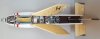
Cutaway model (Pict.02) of a GWS 20 (Guided Weapon System) Seacat short range anti-aircraft missile. The Seacat (Pict.01) is a first generation guided missile, derived from the Australian Malkara anti tank missile, which was found to be much too heavy and cumbersome for a portable anti tank missile, but which formed the basis for the Seacat surface to air missile.
The seacat was meant as a replacement for the aging 40L60 Bofors anti-aircraft guns on ships which had trouble following fast jet fighters, however as the speed of jet fighters increased within a decade from sub sonic to supersonic, the Seacat became obsolete itself as it was a subsonic missile. It was however still suitable for a head on attack of enemy planes. It had to be steered to the target by keeping the flares in the tail fins of the missile over the target and using a thumb joystick to constantly correct the course of the missile towards the target.
The missile was manufactured by Short Brothers in Belfast.
Missile length : 1480 mm (58,29 inch)
Wing span : 650 mm (25,6 inch)
Body diameter motor : 191 mm (7,62 inch)
Missile weight : 62,71 kg (138,25 Lb)
Weight continuous rod warhead : 13,83 kg (30,65 Lb)
Operational range : 500 to 5000 mtrs
Speed : Mach 0,8 (272,24 mtrs/sec).
Operational oil pressure on steering cilinders during flight : between 79 and 103 Bar (1150 to 1500 lbf/ in2)
Guidance system : CLOS (Command Line Of Sight) and radio link
Operators :
Argentina (Seacat/ Tigercat), Australia, Brazil, Chile, Germany, Indonesia, India (Seacat/ Tigercat), Iran (Seacat/ Tigercat), Jordan, Lybia, Malaysia, New Zealand, Netherlands, Nigeria, Philipines, Pakistan, Quatar, South Africa (Tigercat), Sweden, Thailand, United Kingdom (Seacat/ Tigercat), Venezuela , Zimbabwe (Tigercat).
The Seacat / Tigercat has seen service in the following conflicts:
Indo-Paksitani war of 1971, Iran-Iraq war, Falklands war, South African Border war.
Links to interesting you tube movies about the seacat / Tigercat missiles can be found here;
Tigercat Missile (1960-1969) - YouTube
Sea Cat Surface-to-Air Missile GWS20 - YouTube
If the links are gone, look for; ‘Seacat missile’, ‘Tigercat missile’, ‘tigercat missile (1960-1969)’ or ‘short tigercat missile antiaereo (GB)’.
There were several versions of the seacat :
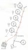
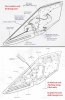
The GWS 20 (described in this posting): the initial version, meant to replace the 40mm/L60 Bofors gun. It was simple in it’s guidance (STD = Simple Tachymetric Director) (Pict.03) which meant the gunner had the target in it’s sight and the rocket had to be manually steered to the target by a small thumb joystick. Flares in the aft fins were used to follow the rocket on it’s way to the target.
The GWS 21, which used a type 262 radar: https://www.radartutorial.eu/06.antennas/Conical Scan.en.html
This offered the possibillity of visual tracking and tracking in the dark, using the radar to guide the seacat to it’s target.
The GWS 22, the seacat with a MRS-3 fire control director and a type 903 radar. This was the first ACLOS-capable (Automatic, Command Line-Of-Sight) Seacat, meaning that it could be fully automatic radar guided, manually radar guided, manualy television guided or visiually guided like the GWS 20.
The GWS 24, which used the used the Italian Alenia Orion RTN-10X fire control system with Type 912 radar. This version was used in the falklands on the type 21 frigate and is said to have downed a Argentinian A-4 Skyhawk.
There also is a land based version of the Seacat, the Tigercat. This was a trailer with three missiles towed by a Landrover. A second landrover towed the trailer with the aiming equipment and the generator.
There is also a training versions with an inert warhead and a dummy versions for training in loading and maintenance available, as well as the Seacat target version that simulated a sea skimming anti shipping missile for anti-shipping missile defence training.
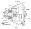
The nose of the missile houses the fuzing system which consists of the following components (Pict 04, 05, 06):
A- The optical sensor
B- The refrigerant system
C- The electronics system
D- The safety and arming system
A - The optical sensor detects infra red light and detonates the warhead if a target is within a 13,7 meters (45 ft) radius. The detection is at a 60 degrees forward angle of the missile’s longitudal axis. The coverage is 360 degrees around and the beam is 8 degrees wide.
Another way the warhead is detonated is caused by a metal strip, appied the lower part of the window; if the window and the strip break upon target contact, this signals the warhead to detonate.
The infra red fuze must also be able to discriminate between sunlight and light emited from the target.
If the target is detected, the light falls through the window on the inside of a ring shaped parabolic mirror that reflects the light tot he centerline of the fuze and makes it pass through a lead telluride filter on the photo conductivce cell.
B - The refrigerant liquid (Freon) is released from a presurized container upon launch and allowed to flow over the base of the photo conductive cell. As the refrigerant has a boiling point of -30 degrees celcius this lowers the temperature of the photo conductive cell which increases the sesitivity and the signal to noise ratio of the sensor.
At the moment the refrigerant liquid is released, a vent valve in the fuze housing is opened, allowing the spent refrigrant vapour to escape into the missile body.
Variations in the current through the photo conductive cell are amplified and when the amplitude of the variations is big enough it will activate the trigger circuit, detonating the warhead.
C - the electronics (Amplifier block) are cast in a resign ring and placed around the photo conductive cell.
D - the safety and arming system is placed on the baseplate of the fuze. It houses;
-the thermal battery that delivers current for one minute only,
-the inertia mechanism that moves a weight with a quadrant arm downward when the missile is launched with 12G. The arm stays locked in it’s lower position if the G force is maintained for at least 0,5 seconds, allowing the release and rotation of the safety and Self Destruct (SD) clockwork.
-the clockwork starts, rotating the safety shutter below the clock in the center line (armed condition), arming the electric detonator for the photo conductive cell after four seconds, so if a target is detected the warhead will detonate. It also starts rotating the shaft that releases a firing pin for the mechanical self destruct mechanism after 35 seconds if no target is hit.
Two types of warhead are available for the live version of the Seacat, the blast warhead (WHD GM HE BLAST) and the HECR (High Explosive Continuous Rod) warhead. In this cutaway model a HECR warhead is placed which will be described here (pict. 07).
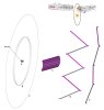
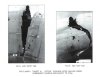
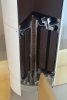
The HECR (Pict 08) warhead consists of an aluminium inner and outer bushing in between which a double bundle of square steel rods 6x6x200mm long runs lengthwise along the circumference of a cilinder filled with an explosive charge. The rods are welded together at alternate ends, thus forming a (folded) uninterrupted circular rod. On the inside of the rods a polysterene liner (black) is placed, enshuring the explosive charge (yellow) does not directy contact the square steel rods, preventing the brisance capability of the explosives from breaking the rods. The initial point of detonation is to be exactly halfway the length of the rods so the rods move outward from the middle, forcibly followed by the welded fore- and aft ends. The expansion of the ring formed by the rods can be seen in picture 09, first a zig zag pattern circle starts forming (B), at the end with the rods at the maximum length but still unbroken at the welds when a circle with a 7,4mtr diameter (C) has been formed. This expansion occures with approximately 1400 meters a second, cutting through an enemy plane like a whip through a piece of paper, practicaly cutting an airplane in half (Pict 10, Victor bomber fuselage). When not cut in half, structural damage to electric wiring, hydraulics, cables, skin and structural parts like girders will be catastrofic. At maximum ring expansion welds break at several places and the loose pieces of rod still move outward, still able to damage a target, although not catastrophic.
The HECR warhead has advantages and disadvantages over a blast fragmentation warhead; if a target is fully hit, the CR warhead’s damage is instantaniously catastrofic, the fragmentation warhead has a better chance of hitting a target as the fragments are thrown around in all directions and not in a single dics, although if no critical parts are hit with the fragmentation warhead it will only leave holes in an aircraft that will not bring it down. However, as fragments move away from the point of detonation, the distance between fragments increases, lowering the chance of hitting a target when distance increases. The CR warhead does not have this disadvantage, as the expanding ring forms a single uniterrupted fragment up to it’s maximum expansion distance.
As precision of missiles improved, the CR warhead faded out of service to be replaced by fragmentation warheads only.
Missiles that used the Continuous Rod warhead were the Seacat, the AIM-7 Sparrow air to air missile, the bloodhound SAM and the RIM-8A Talos missile.
On picture 11 one can see the continuous rod striking steel target panels located near the maximum possible unbroken radius. Both steel target plates and support poles are all cut in half.
The seacat is propulsed with a two stage motor. The aft stage( Pict 12, 13) consists of the boost motor which houses a 6,34 kg cast double base SRS73 powder stick with three circular slots to enlarge the burning surface. A hole is drilled through the center of this powderstick which enables the venturi pipe of the forward -sustainer- motor to pass through the boost motor. The boost motor has a flange placed in the aft end with four slightly angled venturi’s. The motor burns 1,1 seconds and delivers 1270 kg (2800 Lb thrust)
The forward -sustainer- motor is screwed in top of the the boost motor and houses a massive 5,85kg cast double base CP25 powder stick that sustains the speed generated by the -aft- boost motor. The venturi pipe of the sustainer motor runs down through the boost motor and ends in the center of the four venturi’s of the boost motor.
The motor is started by means of a starting cartridge (missing here) placed in the single venturi pipe of the sustainer motor. The flame shoots upward through the pipe and ignites the fuel stick of the sustainer motor and the ignition booster charge placed off center in the base flange of the sustainer motor; it’s flame ignites a circular ignition charge on top of the powderstick of the boost motor through a small channel in a mandifold. So, to ignite the -aft- boost motor, the sustainer motor has to be ignited first. The sustainer motor delivers 68 kg (150 Lb) thrust.
In top of the sustainer motor the accumulator is screwed (pict 14) , consisting of an oval shaped vessel with a membrane in the middle and a valve in it’s base. The top part -above the membrane- contains thin oil, used for steering of the four triangular steering fins of the missile. When the sustainer motor is started, pressurized gas runs through the valve in the lower part of the accumulator, pushing the membrane upward with force, pressurizing the oil, enabeling the missile to be steered by means of the oil served pistons. As the top surface of the valve is larger than the side surface with the bleeding holes, the pressure in the lower space will push the valve closed as soon as the sustainer motor is burned up and the motor pressure suddenly drops, maintaining pressure on the oil.
The boost motor burns 1,1 seconds and accelerates the missile to Mach 0,8 (272 mtr/sec), the sustainer motor maintains this speed for a further 15 seconds under manouevring conditions. After burn out of the sustainer motor, the pressure on the oil is maintaned another 14 seconds, however with a lower pressure, still enanbeling the missile to be steered with a burned out motor.
The missile is connected to the launching pad by means of a shear wire that breaks when enough pressure has been built up, so the missile leaves at full thrust.
To make the motor function propperly the aft flange of both boost- and sustainer motors as well as the in- and outside of the venturi pipe of the sustainer motor are clad with a durestos liners; a heat and abrasion resistant mixture of bakelite and asbestos which prevents the hot gasses of the motors from burning through the aft flanges of both the boost- and sustainer motor.
The inside of the wall of the boost motor has a 2mm thick polyetehene liner to protect the motor casing from excessive heat, the inside wall of the sustainer motor has a heat resistant rubber liner (also appr. 2mm thick) to protect the wall of the motor from excessive heat.
On the lower part of the boost motor a ring is mounted, housing the wing mounting pins of the four aft fins which are stuck in holes in the ring. A longitudal pin placed through the wing mounting pins and ring fixates the wings.
On top of the accumulater the missile stage with the oil filter and gyroscope is placed (Pict 14). The oil filter consists of a sintered filter that allows clean oil through only. After passing this filter the oil is devided over four sets of cilinders, pressurizing the eight pistons, fixating the wings. By bleeding opposite pistons on one side, the wings will rotate to the other side.
The gyroscope is placed in a gimbal, the gimbal is fixated when in rest. The gyroscope wheel contains a rocket motor that induces a high speed spin (36.000 rpm) before the rocket is fired and the gimbal is released after the gyroscope is started and just before launching the missile. This creates a set zero point over the missiles length axis, enabeling the missile to allways keep the forward steering fins in the + position, and returning them to this position when the missile starts roling clockwise, either counterclockwise. This is independent of the steering signals which are given by the gunner to the missile to be steered in the desired direction at any given moment during the flight to the target. In rest, the four wings are fixated in the middle position by means of a mechanism with a retractable radial pin at the root of each wing shaft. After starting the rocket motor, the gas pressure of the motor pressurizes the oil that serves the wing actuators, but also hydraulicly retracts the radial pins that fixate the fins, releasing the fins.
Regretfully the inner works of the gyroscope assembly is missing, so I did not cut the gyroscope housing.
The steering wings of the seacat (Pict 15);
At first glance the wings of the Seacat look like just steering fins, however, this is far from the truth. The two opposite yaw wings house a notch aerial, a plate shaped antenna with slots that match the VHF frequence from the radio equipment served by the gunner. Inside the wing a wire runs to a connection plug that fits the end of the wing shaft. The radio steering signals are transmitted to the electronic package below the warhead where it is translated into a signal to the servo magnets that open and close the oil valves that rotate the shafts over which the wings are placed.
Each of the four wings also has a uninterupted wire placed in the forward edge of each wing, just below the surface. This wire also ends in the connection plug that fits the end of the wing shaft. If- upon inpact with the target- one of these wires in one of the four wings breaks this is translated into a trigger signal to detonate the warhead. These wires are incorperated in the same electric circuit as the breaking wire in he window of the nose fuze.
Some Seacat missiles have a H painted on the pitch wings of the missile, this is the anti-ditching version; a doppler transmitter is placed in one wing, continuously measuring the height of the Seacat over the waves. This is meant to prevent the seacat from ditching into the sea when employed against wave skimming enemy airplanes. With the anti ditching mechanism the missile cannot be steered below six meters above the waves.
The four aft wings are placed 45 degrees rotated compared to the steering fins and are square in shape. All have a longitudal pipe shaped outer end, used to place the tracking flares in. These flares aid the gunner in visualy steering the missile to it’s target.
Regards, DJH
The seacat was meant as a replacement for the aging 40L60 Bofors anti-aircraft guns on ships which had trouble following fast jet fighters, however as the speed of jet fighters increased within a decade from sub sonic to supersonic, the Seacat became obsolete itself as it was a subsonic missile. It was however still suitable for a head on attack of enemy planes. It had to be steered to the target by keeping the flares in the tail fins of the missile over the target and using a thumb joystick to constantly correct the course of the missile towards the target.
The missile was manufactured by Short Brothers in Belfast.
Missile length : 1480 mm (58,29 inch)
Wing span : 650 mm (25,6 inch)
Body diameter motor : 191 mm (7,62 inch)
Missile weight : 62,71 kg (138,25 Lb)
Weight continuous rod warhead : 13,83 kg (30,65 Lb)
Operational range : 500 to 5000 mtrs
Speed : Mach 0,8 (272,24 mtrs/sec).
Operational oil pressure on steering cilinders during flight : between 79 and 103 Bar (1150 to 1500 lbf/ in2)
Guidance system : CLOS (Command Line Of Sight) and radio link
Operators :
Argentina (Seacat/ Tigercat), Australia, Brazil, Chile, Germany, Indonesia, India (Seacat/ Tigercat), Iran (Seacat/ Tigercat), Jordan, Lybia, Malaysia, New Zealand, Netherlands, Nigeria, Philipines, Pakistan, Quatar, South Africa (Tigercat), Sweden, Thailand, United Kingdom (Seacat/ Tigercat), Venezuela , Zimbabwe (Tigercat).
The Seacat / Tigercat has seen service in the following conflicts:
Indo-Paksitani war of 1971, Iran-Iraq war, Falklands war, South African Border war.
Links to interesting you tube movies about the seacat / Tigercat missiles can be found here;
Tigercat Missile (1960-1969) - YouTube
Sea Cat Surface-to-Air Missile GWS20 - YouTube
If the links are gone, look for; ‘Seacat missile’, ‘Tigercat missile’, ‘tigercat missile (1960-1969)’ or ‘short tigercat missile antiaereo (GB)’.
There were several versions of the seacat :
The GWS 20 (described in this posting): the initial version, meant to replace the 40mm/L60 Bofors gun. It was simple in it’s guidance (STD = Simple Tachymetric Director) (Pict.03) which meant the gunner had the target in it’s sight and the rocket had to be manually steered to the target by a small thumb joystick. Flares in the aft fins were used to follow the rocket on it’s way to the target.
The GWS 21, which used a type 262 radar: https://www.radartutorial.eu/06.antennas/Conical Scan.en.html
This offered the possibillity of visual tracking and tracking in the dark, using the radar to guide the seacat to it’s target.
The GWS 22, the seacat with a MRS-3 fire control director and a type 903 radar. This was the first ACLOS-capable (Automatic, Command Line-Of-Sight) Seacat, meaning that it could be fully automatic radar guided, manually radar guided, manualy television guided or visiually guided like the GWS 20.
The GWS 24, which used the used the Italian Alenia Orion RTN-10X fire control system with Type 912 radar. This version was used in the falklands on the type 21 frigate and is said to have downed a Argentinian A-4 Skyhawk.
There also is a land based version of the Seacat, the Tigercat. This was a trailer with three missiles towed by a Landrover. A second landrover towed the trailer with the aiming equipment and the generator.
There is also a training versions with an inert warhead and a dummy versions for training in loading and maintenance available, as well as the Seacat target version that simulated a sea skimming anti shipping missile for anti-shipping missile defence training.
The nose of the missile houses the fuzing system which consists of the following components (Pict 04, 05, 06):
A- The optical sensor
B- The refrigerant system
C- The electronics system
D- The safety and arming system
A - The optical sensor detects infra red light and detonates the warhead if a target is within a 13,7 meters (45 ft) radius. The detection is at a 60 degrees forward angle of the missile’s longitudal axis. The coverage is 360 degrees around and the beam is 8 degrees wide.
Another way the warhead is detonated is caused by a metal strip, appied the lower part of the window; if the window and the strip break upon target contact, this signals the warhead to detonate.
The infra red fuze must also be able to discriminate between sunlight and light emited from the target.
If the target is detected, the light falls through the window on the inside of a ring shaped parabolic mirror that reflects the light tot he centerline of the fuze and makes it pass through a lead telluride filter on the photo conductivce cell.
B - The refrigerant liquid (Freon) is released from a presurized container upon launch and allowed to flow over the base of the photo conductive cell. As the refrigerant has a boiling point of -30 degrees celcius this lowers the temperature of the photo conductive cell which increases the sesitivity and the signal to noise ratio of the sensor.
At the moment the refrigerant liquid is released, a vent valve in the fuze housing is opened, allowing the spent refrigrant vapour to escape into the missile body.
Variations in the current through the photo conductive cell are amplified and when the amplitude of the variations is big enough it will activate the trigger circuit, detonating the warhead.
C - the electronics (Amplifier block) are cast in a resign ring and placed around the photo conductive cell.
D - the safety and arming system is placed on the baseplate of the fuze. It houses;
-the thermal battery that delivers current for one minute only,
-the inertia mechanism that moves a weight with a quadrant arm downward when the missile is launched with 12G. The arm stays locked in it’s lower position if the G force is maintained for at least 0,5 seconds, allowing the release and rotation of the safety and Self Destruct (SD) clockwork.
-the clockwork starts, rotating the safety shutter below the clock in the center line (armed condition), arming the electric detonator for the photo conductive cell after four seconds, so if a target is detected the warhead will detonate. It also starts rotating the shaft that releases a firing pin for the mechanical self destruct mechanism after 35 seconds if no target is hit.
Two types of warhead are available for the live version of the Seacat, the blast warhead (WHD GM HE BLAST) and the HECR (High Explosive Continuous Rod) warhead. In this cutaway model a HECR warhead is placed which will be described here (pict. 07).
The HECR (Pict 08) warhead consists of an aluminium inner and outer bushing in between which a double bundle of square steel rods 6x6x200mm long runs lengthwise along the circumference of a cilinder filled with an explosive charge. The rods are welded together at alternate ends, thus forming a (folded) uninterrupted circular rod. On the inside of the rods a polysterene liner (black) is placed, enshuring the explosive charge (yellow) does not directy contact the square steel rods, preventing the brisance capability of the explosives from breaking the rods. The initial point of detonation is to be exactly halfway the length of the rods so the rods move outward from the middle, forcibly followed by the welded fore- and aft ends. The expansion of the ring formed by the rods can be seen in picture 09, first a zig zag pattern circle starts forming (B), at the end with the rods at the maximum length but still unbroken at the welds when a circle with a 7,4mtr diameter (C) has been formed. This expansion occures with approximately 1400 meters a second, cutting through an enemy plane like a whip through a piece of paper, practicaly cutting an airplane in half (Pict 10, Victor bomber fuselage). When not cut in half, structural damage to electric wiring, hydraulics, cables, skin and structural parts like girders will be catastrofic. At maximum ring expansion welds break at several places and the loose pieces of rod still move outward, still able to damage a target, although not catastrophic.
The HECR warhead has advantages and disadvantages over a blast fragmentation warhead; if a target is fully hit, the CR warhead’s damage is instantaniously catastrofic, the fragmentation warhead has a better chance of hitting a target as the fragments are thrown around in all directions and not in a single dics, although if no critical parts are hit with the fragmentation warhead it will only leave holes in an aircraft that will not bring it down. However, as fragments move away from the point of detonation, the distance between fragments increases, lowering the chance of hitting a target when distance increases. The CR warhead does not have this disadvantage, as the expanding ring forms a single uniterrupted fragment up to it’s maximum expansion distance.
As precision of missiles improved, the CR warhead faded out of service to be replaced by fragmentation warheads only.
Missiles that used the Continuous Rod warhead were the Seacat, the AIM-7 Sparrow air to air missile, the bloodhound SAM and the RIM-8A Talos missile.
On picture 11 one can see the continuous rod striking steel target panels located near the maximum possible unbroken radius. Both steel target plates and support poles are all cut in half.
The seacat is propulsed with a two stage motor. The aft stage( Pict 12, 13) consists of the boost motor which houses a 6,34 kg cast double base SRS73 powder stick with three circular slots to enlarge the burning surface. A hole is drilled through the center of this powderstick which enables the venturi pipe of the forward -sustainer- motor to pass through the boost motor. The boost motor has a flange placed in the aft end with four slightly angled venturi’s. The motor burns 1,1 seconds and delivers 1270 kg (2800 Lb thrust)
The forward -sustainer- motor is screwed in top of the the boost motor and houses a massive 5,85kg cast double base CP25 powder stick that sustains the speed generated by the -aft- boost motor. The venturi pipe of the sustainer motor runs down through the boost motor and ends in the center of the four venturi’s of the boost motor.
The motor is started by means of a starting cartridge (missing here) placed in the single venturi pipe of the sustainer motor. The flame shoots upward through the pipe and ignites the fuel stick of the sustainer motor and the ignition booster charge placed off center in the base flange of the sustainer motor; it’s flame ignites a circular ignition charge on top of the powderstick of the boost motor through a small channel in a mandifold. So, to ignite the -aft- boost motor, the sustainer motor has to be ignited first. The sustainer motor delivers 68 kg (150 Lb) thrust.
In top of the sustainer motor the accumulator is screwed (pict 14) , consisting of an oval shaped vessel with a membrane in the middle and a valve in it’s base. The top part -above the membrane- contains thin oil, used for steering of the four triangular steering fins of the missile. When the sustainer motor is started, pressurized gas runs through the valve in the lower part of the accumulator, pushing the membrane upward with force, pressurizing the oil, enabeling the missile to be steered by means of the oil served pistons. As the top surface of the valve is larger than the side surface with the bleeding holes, the pressure in the lower space will push the valve closed as soon as the sustainer motor is burned up and the motor pressure suddenly drops, maintaining pressure on the oil.
The boost motor burns 1,1 seconds and accelerates the missile to Mach 0,8 (272 mtr/sec), the sustainer motor maintains this speed for a further 15 seconds under manouevring conditions. After burn out of the sustainer motor, the pressure on the oil is maintaned another 14 seconds, however with a lower pressure, still enanbeling the missile to be steered with a burned out motor.
The missile is connected to the launching pad by means of a shear wire that breaks when enough pressure has been built up, so the missile leaves at full thrust.
To make the motor function propperly the aft flange of both boost- and sustainer motors as well as the in- and outside of the venturi pipe of the sustainer motor are clad with a durestos liners; a heat and abrasion resistant mixture of bakelite and asbestos which prevents the hot gasses of the motors from burning through the aft flanges of both the boost- and sustainer motor.
The inside of the wall of the boost motor has a 2mm thick polyetehene liner to protect the motor casing from excessive heat, the inside wall of the sustainer motor has a heat resistant rubber liner (also appr. 2mm thick) to protect the wall of the motor from excessive heat.
On the lower part of the boost motor a ring is mounted, housing the wing mounting pins of the four aft fins which are stuck in holes in the ring. A longitudal pin placed through the wing mounting pins and ring fixates the wings.
On top of the accumulater the missile stage with the oil filter and gyroscope is placed (Pict 14). The oil filter consists of a sintered filter that allows clean oil through only. After passing this filter the oil is devided over four sets of cilinders, pressurizing the eight pistons, fixating the wings. By bleeding opposite pistons on one side, the wings will rotate to the other side.
The gyroscope is placed in a gimbal, the gimbal is fixated when in rest. The gyroscope wheel contains a rocket motor that induces a high speed spin (36.000 rpm) before the rocket is fired and the gimbal is released after the gyroscope is started and just before launching the missile. This creates a set zero point over the missiles length axis, enabeling the missile to allways keep the forward steering fins in the + position, and returning them to this position when the missile starts roling clockwise, either counterclockwise. This is independent of the steering signals which are given by the gunner to the missile to be steered in the desired direction at any given moment during the flight to the target. In rest, the four wings are fixated in the middle position by means of a mechanism with a retractable radial pin at the root of each wing shaft. After starting the rocket motor, the gas pressure of the motor pressurizes the oil that serves the wing actuators, but also hydraulicly retracts the radial pins that fixate the fins, releasing the fins.
Regretfully the inner works of the gyroscope assembly is missing, so I did not cut the gyroscope housing.
The steering wings of the seacat (Pict 15);
At first glance the wings of the Seacat look like just steering fins, however, this is far from the truth. The two opposite yaw wings house a notch aerial, a plate shaped antenna with slots that match the VHF frequence from the radio equipment served by the gunner. Inside the wing a wire runs to a connection plug that fits the end of the wing shaft. The radio steering signals are transmitted to the electronic package below the warhead where it is translated into a signal to the servo magnets that open and close the oil valves that rotate the shafts over which the wings are placed.
Each of the four wings also has a uninterupted wire placed in the forward edge of each wing, just below the surface. This wire also ends in the connection plug that fits the end of the wing shaft. If- upon inpact with the target- one of these wires in one of the four wings breaks this is translated into a trigger signal to detonate the warhead. These wires are incorperated in the same electric circuit as the breaking wire in he window of the nose fuze.
Some Seacat missiles have a H painted on the pitch wings of the missile, this is the anti-ditching version; a doppler transmitter is placed in one wing, continuously measuring the height of the Seacat over the waves. This is meant to prevent the seacat from ditching into the sea when employed against wave skimming enemy airplanes. With the anti ditching mechanism the missile cannot be steered below six meters above the waves.
The four aft wings are placed 45 degrees rotated compared to the steering fins and are square in shape. All have a longitudal pipe shaped outer end, used to place the tracking flares in. These flares aid the gunner in visualy steering the missile to it’s target.
Regards, DJH
Attachments
-
 Pict 01 - GWS 20 Seacat.jpg259.1 KB · Views: 56
 -
 Pict 02 - GWS 20 Seacat cutaway.jpg298.5 KB · Views: 70
 -
 Pict 03 - seacat steering.jpg69.6 KB · Views: 47
 -
 Pict 04 - fuzing system seacat.jpg81.4 KB · Views: 40
 -
 Pict 05 fuze dome window.jpg28.9 KB · Views: 37
 -
 Pict 06 - Safety and arming mechanism seacat fuze..jpg166.9 KB · Views: 39
 -
 Pict 07 - GWS 20 Seacat nose cutaway.jpg297.3 KB · Views: 49
 -
 Pict 08 - GWS 20 HECR Continuous rod warhead replica.jpg303.8 KB · Views: 40
 -
 Pict 09 - HECR warhead expansion.jpg217.8 KB · Views: 31
 -
 Pict 10 - Victor bomber fuselage HECR test.jpg115.5 KB · Views: 33
 -
 Pict 11 - CR warhead exploding.jpg184.1 KB · Views: 33
 -
 Pict 12 - GWS 20 Seacat igniter.jpg275.1 KB · Views: 34
 -
 Pict 13 - GWS 20 Seacat lower engine and nozzles.jpg279.6 KB · Views: 28
 -
 Pict 14 - GWS 20 Seacat accumulator.jpg306.5 KB · Views: 35
 -
 Pict 15 - Steering fin.jpg177.5 KB · Views: 28
 -
 Pict 16- Tigercat add.jpg186.5 KB · Views: 39
Last edited: