BOUGAINVILLE
Well-Known Member
Hi everyone,
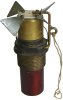
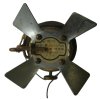
Here is one of my latest additions to my collection. It is a Japanese Navy Air Force A-3(a) mechanical impact bomb nose fuze.
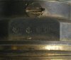
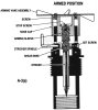
NAVY TYPE 97, Mk II, IMPACT FUZE, MODEL 2
KEY FOR ILLUSTRATION:
1 ARMING VANE
2 SCREW
3 LARGE HEADED SCREW
4 BRASS CAP
5 ARMING WIRE
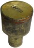
6 PRESSURE SLEEVE
7 WASHER
8 SHEAR WIRE
9 TRANSIT SAFETY FORK
10 STRIKER SPINDLE
11 FUZE BODY
12 STRIKER NEEDLE
13 SET SCREW
14 BRASS LOOP
15 INTERNAL THREAD
US DESIGNATION
Japanese bomb fuze - A.3(A)
TYPE
NAVY Air force mechanical impact nose fuze to which a Navy type standard gaine or magazine can be fitted.
BOMBS IN WHICH USED
a) Incorporating a gaine ‑
60 Kg, Type 97. GP - Navy type
60 Kg, Type 98, GP - " "
63 Kg, Type 99, SAP- " "
250 Kg, Type , GP - " "
250 Kg, Type , SAP- " "
b) Incorporating a magazine ‑
60 Kg, Type 97, Incendiary (electron fire-pots)
60 Kg, Type 98, " (solid oil)
250 Kg, Type, " (electron/steel Cylinders)
COLOUR
Natural BRASS.
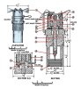
DESCRIPTION (See diagram)
The fuze body (11) houses the striker mechanism only. A striker spindle (10) passing through the centre of the body is left-hand threaded at the upper end to take a pressure sleeve (6). The spindle is prevented from rotating by a set screw (13) and a safety shear wire (8). A large-headed screw (3) threaded right-hand screws into the top of the spindle to prevent the pressure sleeve unscrewing com­pletely from the spindle.
Four screws (2) pass through the centre flat of the 4-bladed arming vanes (1) and the top of the brass cap (4) and screw into the pressure sleeve (6), thus the whole assembly (1), (4) and (6) is free to rotate.
A steel striker needle (12) screws into the lower end of the spindle. The lower end of the fuze body is threaded (15) to take a Navy type standard gaine or magazine.
A 3-pronged transit safety fork (9) prevents ro­tation of the vanes. This is withdrawn on loading into the bomb rack.
An arming wire (5) is soldered at one end to the side of the brass cap (4), taken 13/4 turns around the brass cap, then passed through the brass loop (14) ending in a loop
ACTION
On release, the arming wire (5) gives the vanes their initial start overcoming any binding between the brass cap and fuse body. The vanes rotate clockwise and the as­sembly (1), (4) and (6) is raised outward until the pressure sleeve is stopped by the large screw (3).
On impact, the brass cap and pressure sleeve assembly forces the spindle inwards shearing the safety wire, and the initiator is pierced by the striker needle.
DISPOSAL
a) Destruction. When the bomb is to be destroyed in situ, the fuze should be blown up with the bomb
b) Rendering safe for handling. Secure the brass cap (and therefore the spindle) against movement in any direction with adhesive tape and pliable wire. If Special BD Tool No 1 is used, apply so as to grip both the Cap and fuze body or, if pos­sible, the fuze body immediately below the cap.
c) Fuze removal.
i. Perform (b)above
ii. Remove grub screw securing fuze to the bomb
iii. Unscrew fuze by means of the remote con­trolled Fuze Extractor Design III (Aust.) if available.
Alternatively, unscrew fuze only a partial turn with Special BD Tool No 5 (spanner) or Stillson Wrench and complete removal by re­mote control.
Cheers,
BOUGAINVILLE
Here is one of my latest additions to my collection. It is a Japanese Navy Air Force A-3(a) mechanical impact bomb nose fuze.
NAVY TYPE 97, Mk II, IMPACT FUZE, MODEL 2
KEY FOR ILLUSTRATION:
1 ARMING VANE
2 SCREW
3 LARGE HEADED SCREW
4 BRASS CAP
5 ARMING WIRE
6 PRESSURE SLEEVE
7 WASHER
8 SHEAR WIRE
9 TRANSIT SAFETY FORK
10 STRIKER SPINDLE
11 FUZE BODY
12 STRIKER NEEDLE
13 SET SCREW
14 BRASS LOOP
15 INTERNAL THREAD
US DESIGNATION
Japanese bomb fuze - A.3(A)
TYPE
NAVY Air force mechanical impact nose fuze to which a Navy type standard gaine or magazine can be fitted.
BOMBS IN WHICH USED
a) Incorporating a gaine ‑
60 Kg, Type 97. GP - Navy type
60 Kg, Type 98, GP - " "
63 Kg, Type 99, SAP- " "
250 Kg, Type , GP - " "
250 Kg, Type , SAP- " "
b) Incorporating a magazine ‑
60 Kg, Type 97, Incendiary (electron fire-pots)
60 Kg, Type 98, " (solid oil)
250 Kg, Type, " (electron/steel Cylinders)
COLOUR
Natural BRASS.
DESCRIPTION (See diagram)
The fuze body (11) houses the striker mechanism only. A striker spindle (10) passing through the centre of the body is left-hand threaded at the upper end to take a pressure sleeve (6). The spindle is prevented from rotating by a set screw (13) and a safety shear wire (8). A large-headed screw (3) threaded right-hand screws into the top of the spindle to prevent the pressure sleeve unscrewing com­pletely from the spindle.
Four screws (2) pass through the centre flat of the 4-bladed arming vanes (1) and the top of the brass cap (4) and screw into the pressure sleeve (6), thus the whole assembly (1), (4) and (6) is free to rotate.
A steel striker needle (12) screws into the lower end of the spindle. The lower end of the fuze body is threaded (15) to take a Navy type standard gaine or magazine.
A 3-pronged transit safety fork (9) prevents ro­tation of the vanes. This is withdrawn on loading into the bomb rack.
An arming wire (5) is soldered at one end to the side of the brass cap (4), taken 13/4 turns around the brass cap, then passed through the brass loop (14) ending in a loop
ACTION
On release, the arming wire (5) gives the vanes their initial start overcoming any binding between the brass cap and fuse body. The vanes rotate clockwise and the as­sembly (1), (4) and (6) is raised outward until the pressure sleeve is stopped by the large screw (3).
On impact, the brass cap and pressure sleeve assembly forces the spindle inwards shearing the safety wire, and the initiator is pierced by the striker needle.
DISPOSAL
a) Destruction. When the bomb is to be destroyed in situ, the fuze should be blown up with the bomb
b) Rendering safe for handling. Secure the brass cap (and therefore the spindle) against movement in any direction with adhesive tape and pliable wire. If Special BD Tool No 1 is used, apply so as to grip both the Cap and fuze body or, if pos­sible, the fuze body immediately below the cap.
c) Fuze removal.
i. Perform (b)above
ii. Remove grub screw securing fuze to the bomb
iii. Unscrew fuze by means of the remote con­trolled Fuze Extractor Design III (Aust.) if available.
Alternatively, unscrew fuze only a partial turn with Special BD Tool No 5 (spanner) or Stillson Wrench and complete removal by re­mote control.
Cheers,
BOUGAINVILLE
Attachments
Last edited: