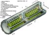
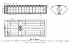
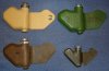
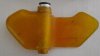
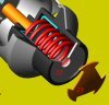
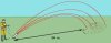
Cutaway model of a Rusian PFM-1(S) anti personel mine. The mine is a copy of the American BLU-43/B of BLU-44/B “Dragontooth” mine, however bigger. The mine is a hydraulicly activated air dropped dispenser mine. Due to it’s shape –borrowed from nature’s earonautical design of a maple seed- it does not need a parachute, it will descend to the ground rotating on it’s wing, minimalizing the impact force.
This mine was used in great numbers by the Russian army in Afghanistan, regretfully it was often seen as an interesting “toy” by children due to it’s weird shape, with dramatic consequences for the child.
The PFM-1(S) was therefore one of the main reasons for the call for a worldwide ban on landmines (Otowa Treaty), forbidding the design, manufacture, storage and use of landmines.
The PFM-1 has no self destuct mecanism, the PFM-1S has a self destruct mechanism.
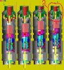
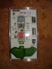
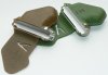
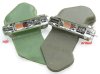
The PFM-1 can be found in the following colours: Leaf green, Brown and Sand colour.
The PFM-1 is also known under the nicknames “Butterfly mine” or “Green Parrot”
Method of dispersion:
The PFM-1(S) can be dispersed in the following ways:
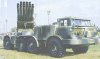
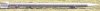
-312 mines form the cargo of a 9H128K3 artillery rocket. The warhead of this rocket contains 12 pcs of 9N233 dispensers which contain 26 mines each.
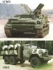
-11520/12960 mines in the VSM-1 helicopter (Mi-8T) borne system with 180 dispensers KSF-1/ KSF-1S 0.5 (72 mines) or KSF-1S (64 mines) dispensers (the KSF 0.5 holds a 50/50% mix of PFM-11 and PFM-1S mines).
-Tracked mine layer UGMZ (no further info
-5670/6480 mines in the VSM lorry mounted system with 90 dispensers KSF-1/ KSF-1S.
-PKM man carried system with 64/72 mines.
-KMG-U aircraft dispenser
-122mm BM21 artillery rocket
Data PFM-1(S):
Length : 120mm
width: 60mm
Thickness : 19mm
Weight of complete mine : 80 gram
Weight liquid explosive charge: 40 gram VS-6D
Arming time : between 1 and 10 minutes
Operation force : plm. 5-25 kg according to russian documents
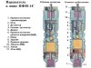
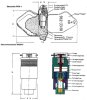
Part list:
1- Upper part fuze body.
2- Lower part fuze body.
3- Connection ring.
4- Dash pot.
5- Silicon grease.
6- Transport safety pin.
7- Guidance ring.
8- Cap.
9- Spring under cap.
10- Firing pin housing.
11- Firing pin.
12- Firing pin spring.
13- Steel Ball.
14- Collar bush.
15- Firing cap housing (ring).
16- Firing cap.
17- Detonator.
18- Rubber bellow.
19- Arming pin.
20- Piston.
21- Spring.
22- Cover disc with small central hole.
23- Cover disc with three slots on circumference.
I have no name or typenumber for the fuze, so I made a description.
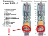
Functioning of the fuze:
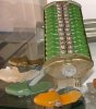
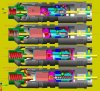
Before relase from the dispenser , the mines are stacked in pair of two in the dispenser, fuze against fuze. Between both fuzes a safety clip is placed which keeps both transport safety pins (6) in lower position, unable to rise so the mine cannot be armed while in the dispenser.
Only after ejection of the mine from the dispenser the set falls apart, ripping away the safety clip. The transport safety pin (6) starts moving upward, pushed by the spring (9) under the cap (8), however reduced in it’s movement speed by the viscuous silicon grease (5) in the dash pot.
On the lower part of the fuze the arming pin (19) in the lower dash pot (4) is pushed upward by the spring (21) under the piston (20). In this piston a small (0,2mm dia) hole is drilled, below that two discs are placed , one with a central hole (22) and one with three slots machined on the circumference. Through these openings, the liquid explosive main charge flows during arming, creating a reduced speed upward movement of the arming pin (19).
The firing pin (11) is blocked in it’s downward movement by a steel ball (13), which –on it’s turn- is kept in inward position by a collar bush (14). This collar bush is mounted in the lower fuze housing and kept in a fixed position by three indentations in the fuze housing.
The firing cap housing (15) is kept in an angled position compared to the centerline of the fuze by means of a chamfered side of the lower half of the firing pin housing (10), enshuring the firing pin (11) cannot reach the firing cap (16) in safe position.
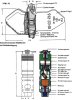
If the transport safety pin (6) moves upward, the arming pin (19), -pushed upward by the spring (21) under the piston (20)- starts pushing the detonator (17), The firing cap housing (15),and the firing pin housing (10) upward, however retarded in it’s upward movement by the transport safety pin (6) moving upward slowly through the thick silicon grease (5). While moving upward, the chamfered edge of the firing pin housing (10) dissapears into the collar bush (14), allowing the firing cap housing (15) with the firing cap (16) to rotate in line with the firing pin (11) and detonator (17). If the arming pin (19) is fully extended it has moved up this train of parts so far that the ball (13) has crept up till just 0,5 mm under the upper rim of the collar bush (14).
The transport safety pin (6) however rises another three millimeter under influence of the spring (9) under the cap (8), allowing the firing pin housing (10) to move upward freely. The mine is now armed.
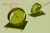
If an operation pressure of approximately 5 kg is applied to the liquid container of the mine, the hydraulic pressure will push away the rubber membrane (18), pushing up the detonator (17), firing cap housing (15) and firing pin housing (10) parts train until the ball is released sideways and the firing pin moves into the firing cap, igniting the detonator and the mine.
Regards, DJH
This mine was used in great numbers by the Russian army in Afghanistan, regretfully it was often seen as an interesting “toy” by children due to it’s weird shape, with dramatic consequences for the child.
The PFM-1(S) was therefore one of the main reasons for the call for a worldwide ban on landmines (Otowa Treaty), forbidding the design, manufacture, storage and use of landmines.
The PFM-1 has no self destuct mecanism, the PFM-1S has a self destruct mechanism.
The PFM-1 can be found in the following colours: Leaf green, Brown and Sand colour.
The PFM-1 is also known under the nicknames “Butterfly mine” or “Green Parrot”
Method of dispersion:
The PFM-1(S) can be dispersed in the following ways:
-312 mines form the cargo of a 9H128K3 artillery rocket. The warhead of this rocket contains 12 pcs of 9N233 dispensers which contain 26 mines each.
-11520/12960 mines in the VSM-1 helicopter (Mi-8T) borne system with 180 dispensers KSF-1/ KSF-1S 0.5 (72 mines) or KSF-1S (64 mines) dispensers (the KSF 0.5 holds a 50/50% mix of PFM-11 and PFM-1S mines).
-Tracked mine layer UGMZ (no further info
-5670/6480 mines in the VSM lorry mounted system with 90 dispensers KSF-1/ KSF-1S.
-PKM man carried system with 64/72 mines.
-KMG-U aircraft dispenser
-122mm BM21 artillery rocket
Data PFM-1(S):
Length : 120mm
width: 60mm
Thickness : 19mm
Weight of complete mine : 80 gram
Weight liquid explosive charge: 40 gram VS-6D
Arming time : between 1 and 10 minutes
Operation force : plm. 5-25 kg according to russian documents
Part list:
1- Upper part fuze body.
2- Lower part fuze body.
3- Connection ring.
4- Dash pot.
5- Silicon grease.
6- Transport safety pin.
7- Guidance ring.
8- Cap.
9- Spring under cap.
10- Firing pin housing.
11- Firing pin.
12- Firing pin spring.
13- Steel Ball.
14- Collar bush.
15- Firing cap housing (ring).
16- Firing cap.
17- Detonator.
18- Rubber bellow.
19- Arming pin.
20- Piston.
21- Spring.
22- Cover disc with small central hole.
23- Cover disc with three slots on circumference.
I have no name or typenumber for the fuze, so I made a description.
Functioning of the fuze:
Before relase from the dispenser , the mines are stacked in pair of two in the dispenser, fuze against fuze. Between both fuzes a safety clip is placed which keeps both transport safety pins (6) in lower position, unable to rise so the mine cannot be armed while in the dispenser.
Only after ejection of the mine from the dispenser the set falls apart, ripping away the safety clip. The transport safety pin (6) starts moving upward, pushed by the spring (9) under the cap (8), however reduced in it’s movement speed by the viscuous silicon grease (5) in the dash pot.
On the lower part of the fuze the arming pin (19) in the lower dash pot (4) is pushed upward by the spring (21) under the piston (20). In this piston a small (0,2mm dia) hole is drilled, below that two discs are placed , one with a central hole (22) and one with three slots machined on the circumference. Through these openings, the liquid explosive main charge flows during arming, creating a reduced speed upward movement of the arming pin (19).
The firing pin (11) is blocked in it’s downward movement by a steel ball (13), which –on it’s turn- is kept in inward position by a collar bush (14). This collar bush is mounted in the lower fuze housing and kept in a fixed position by three indentations in the fuze housing.
The firing cap housing (15) is kept in an angled position compared to the centerline of the fuze by means of a chamfered side of the lower half of the firing pin housing (10), enshuring the firing pin (11) cannot reach the firing cap (16) in safe position.
If the transport safety pin (6) moves upward, the arming pin (19), -pushed upward by the spring (21) under the piston (20)- starts pushing the detonator (17), The firing cap housing (15),and the firing pin housing (10) upward, however retarded in it’s upward movement by the transport safety pin (6) moving upward slowly through the thick silicon grease (5). While moving upward, the chamfered edge of the firing pin housing (10) dissapears into the collar bush (14), allowing the firing cap housing (15) with the firing cap (16) to rotate in line with the firing pin (11) and detonator (17). If the arming pin (19) is fully extended it has moved up this train of parts so far that the ball (13) has crept up till just 0,5 mm under the upper rim of the collar bush (14).
The transport safety pin (6) however rises another three millimeter under influence of the spring (9) under the cap (8), allowing the firing pin housing (10) to move upward freely. The mine is now armed.
If an operation pressure of approximately 5 kg is applied to the liquid container of the mine, the hydraulic pressure will push away the rubber membrane (18), pushing up the detonator (17), firing cap housing (15) and firing pin housing (10) parts train until the ball is released sideways and the firing pin moves into the firing cap, igniting the detonator and the mine.
Regards, DJH
Attachments
-
 Fuze PFM-1 dwg-1.jpg90.5 KB · Views: 303
 -
 Fuze PFM-1 dwg-2.jpg56.1 KB · Views: 212
 -
 PFM-1 practice mines.JPG74.4 KB · Views: 229
 -
 uragan-4.jpg11.5 KB · Views: 179
 -
 220 mm 9N128K3 rocket.jpg8 KB · Views: 172
 -
 mine laying vehicles.jpg22.9 KB · Views: 165
 -
 PKM manual laying system 1.JPG12.3 KB · Views: 159
 -
 PKM manual laying system 2.JPG8.2 KB · Views: 174
 -
 PFM-1 safe and armed.jpg92.4 KB · Views: 301
Last edited: