Hi Bellifortis,
Sorry for the delay, Ive only just found your last post and question. As you say, the fuze is a pure time fuze.
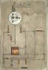
I understand most vibration switches required an acceleration of around 50G to make a contact. Assuming the two vibration switches in this El. Z. (32) are these type, then I doubt that they would operate on release of the bomb. They are designed purely to operate when the bomb impacts.
Also if the ground connection at f is to be made immediately on bomb release, then it would make more sense to connect f to bz.
Operation.
With the plunger depressed (bomb in bomb bay):
C(g-b) is charged
C(a-bsp) is charged
The spring clip connection to ground (below the Sx5) allows reservoir C(a-bsp) to charge.
There are no ground connections to C(c-bz), C(d-bz) and C(e-f), so these capacitors do not charge.
Plunger released (bomb released):
Ground connection bz is made so C(c-bz) and C(d-bz) charge from the reservoir C(a-bsp) during the travel of the bomb.
Bomb impacts:
Switch(g-h) operates and C25 fires to complete the ground to the main igniter circuit (glow tube, Sx6, etc).
Switch(c-Sx5) operates and C(c-bz) fires Sx5, removing the ground spring clip connection and thereby removing the ground connection to C(a-bsp).
C(e-f) is charged from C(d-bz) via resistor R(d-e). When the voltage on C(e-f) equals the striking voltage of the glow tube, the main igniter Sx6 fires and the bomb explodes.
Without knowing the resistor values it is not possible to say what the timing values are for this fuze. Given the ratio of C(d-bz) to C(e-f) as exactly 2:1, and that the primary reservoir C(a-bsp) is not used to charge C(e-f) directly (it is actually removed from the circuit and C(d-bz) charges C(e-f) ), then the delay is short, perhaps 0.1-10s, and programmable, proportional to the initial voltage applied from the aircraft. This might suggest the fuze was designed for an armour or bunker piercing bomb, using an accurate electrical variable time delay instead of a pyrotechnic delay pellet.
Tom.


.jpg")