As this posting contains a lot of pictures accompanying the text, pictures and partnumbers are described in the following way:
(P01-2 ) = (Picture 01-partnumber 2 ).
(P01, P04-2 ) = (Picture 01, Picture 04 -partnumber 2 ).
(P10) = full picture 10
The easiest way to read this posting is by placing the pictures in a map on your desktop so you can easily browse up and down the pictures, and use a printed text.
------------------------------------------------------------------------------------------------------------------------------------------------------------------------------------
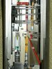
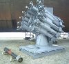
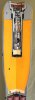
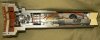
Cutaway model of a Russian Naval RGB60 rocket propelled depth charge (P01, P02 ).
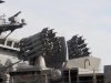
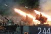
The RGB60 rocket propelled depth charge is used to destroy submarines through salvo fire. It is fired from the RBU6000-Smerch2 depth charge launcher. It was developed by the Moscow institute of thermal technology.
The launcher is manufactured by the Zavod artillery plant No.9 in Russia.
The RBU6000-Smerch2 depth charge launcher was designed in 1960. A working model was ready in 1961, and the weapon was put into full Warshaw pact fleet service in 1964. It was mounted on a wide array of Warsaw-pact naval surface vessels.
The RBU-6000 consists of 12 launching pipes, placed in a horseshoe shaped array. Rockets can be fired in salvos of 1, 2, 4, 8 or 12 rounds rippled.
Reloading is automatic by the -below deck- UP60 storage and reloading system, which places the rockets in the launcher one by one. The magazine capacity of the UP60 storage system is either 72 or 90 rounds per RBU6000 launcher system.
https://www.youtube.com/watch?v=0EW196Ka2so (RBU-6000 firing the homing 90R missile)
Loading of the RBU-6000 system aboard the Russian Grisha class anti submarine corvette ‘Albatros’ can be observed in this You Tube movie from 3:12 min to 4:12 min.
https://www.youtube.com/watch?v=wd5jVBhSJfI
The Soviet navy estimated that with using this system, the time between first sonar contact of the target submarine and it’s destruction would be between 60-90 seconds, with a kill probability of 0.8 at the first salvo.
To understand the functioning of this rocket and the launcher system, one first has to understand the dynamics of the submarine hunt.
An enemy submarine is an object constantly moving in three dimensions; up and down, left and right, forward and afterward, with varying speed. The submarine hunter moves in two dimensions; forward and afterward, left and right, but separate from that it’s hull also moves in three directions over the waves when it rolls, pitches and sheers. As one will understand this makes aiming quite an art.
When shooting at the maximum range (5500 mtrs in 10 seconds flight time) at an enemy submarine at the RGB60’s deepest working depth of 500mtrs. (43,5 seconds with a sink rate of 11,5 mtrs/sec), one will have to make an educated guess at which coordinates to expect the enemy submarine 53,5 seconds later.
The RBU6000 launcher is remotely directed by the PUSB Burya fire control system, that plots the cource and speed of the enemy submarine by sonar contact, and calculates/predicts on which coordinates -compared to the hunter’s position and speed upon firing- to shoot, so the enemy submarine and the depth charges meet.
Apart from aiming at the target, the rolling, pitching and sheering of the ship have to be compensated for seperately.
One can see this rolling compensation movement in this You Tube movie: https://www.youtube.com/watch?v=sdIvoPbpeyE
On the front end of the launching pipe of the RBU6000 one can see the fuze setter. This electric setting tool is pressed on top of the UDW60 fuze (P07 ) and keeps setting the time until the moment of launch, when the rocket leaving the launching pipe flips it over in the outer position. This ensures continuous time setting up to the moment of launch.
General info RGB60 depth charge:
Caliber of the rocket : 212mm
Length of the rocket : 1830mm
Weight of the rocket : 113,5 kg
Weight of the explosive charge : 23,5 kg
Minimal range : 300 mtr.
Maximum range : 5500 mtr.
Working depth range : Minimum 10 mtrs, maximum 500 mtrs
Sinking rate in seawater (constant) : 11,5 mtrs/sec
The RGB60 rocket propelled depth charge is build up of the following main parts:
I - warhead
II - rocket motor
III - stabilizer
IV - time and impact fuze UDW60
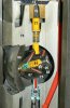
I- The warhead (P03 ) ;
The warhead is composed of a heavy steel nosepiece (P03-1 ) with a rounded nose, to which the sheet metal vessel (P03-2 ) is welded to the base. The base of the vessel reduces in diameter to receive the closing cap (P03, P04-3 ). In the center of the nosepiece a threaded hole is machined to receive the UDW60 fuze. A sheet metal tube (P03-4 ) is welded to the base of the hole in the nosepiece to house the fuze.
The explosive charge (P03, P04-5 ) is cast in the warhead from the base, the last inch being a separate cast of Trotyl (P03, P04,-6 ). Below this layer of Trotyl a 3mm thick “Textylscheibe” (P03, P04-7 ) –synthetic heat resistant material- is placed, protecting the explosive charge from the radiation heat of the motor below when launched.
The closing cap is screwed over the base of the warhead. It is threaded also on the outside to receive the pipe piece of the forward motor (P03, P04-8 ).
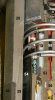
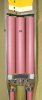
II- The rocket motor (P04, P05, P06 );
The rocket motor is composed of two separate motors: the forward motor (P04 ) and the rear motor (P05, P06 ).
Both motors are connected by a connection piece (P05-9 ).
The forward motor (P04 ):
The forward motor is a piece of pipe (P03, P04-8 ) that is threaded on the inside in top and base. In top is screwed over the base cap of the warhead, at the base it is screwed over the connection piece. Seven powder sticks (P04, P05-10 ) -with one hole in the center- are placed in the forward motor, locked up by a steel grid (P03, P04-11 ) on top.
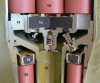
The connection piece is a pipe piece (P05, P06 -12 ) with a flange welded on top (P05-9 ) which is externally threaded at the top part of the flange to receive the pipe piece of the upper rocket motor, and internally threaded at the lower part of the flange to receive the pipe piece of the lower rocket motor.
In the base of the forward motor, -on top if the connection piece- the grid (P05-13 ) is placed. The grid also houses the black powder booster charge (P05-14 ). At the base of the grid, below the booster charge the electric ignition charge (P05-15 ) is placed. Its wires (P05, P06-16 ) run down the pipe of the connection piece and end in an electric connection plug (P06-17 ) in the venturi (P06-18 ) of the forward motor at the base of the rocket.
Two spring loaded non-return valves (P05-19 ) are placed in the flange of the connection piece, connecting the forward and rear motor in the direction forward –rearward.
This is done for the following reason: when firing the missile it should hit the waves at a near vertical angle to positively activate the fuze. When the maximum range is 5500 mtrs, it means the rocket needs a certain speed to get that far and land in the waves near vertical. At short range this means the rocket has a too high speed and will hit the waves near horizontal.
To solve this problem, the motor is divided in two stages, a short range motor (300-1500 mtrs), and a long range motor (1500-5500 mtrs).
When short range is required, only the rear motor is activated, inducing spin on the rocket when fired. The non return valves are pushed closed.
If the long range is required, the forward motor is ignited. The pressurized gasses of the forward motor push open the non return valve and ignite the rear motor. Both motors are now used.
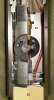
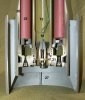
The rear motor (P05, P06-20 ):
The rear motor is a pipe piece (P05 P06-20 ), externally threaded in top and internally threaded at the base. In top it is screwed in the connection piece (P05-9 ). In the base a flange (P06-21 ) is screwed with a circular array of 14 venturi holes (P06-22 ) drilled at a 5 degree angle to induce spin to stabilize the rocket in flight. In the center of the flange a hole is drilled to receive the pipe of the connection piece (P06-12 ). The venturi (P06-18 ) is screwed into the base of this pipe, which also serves as a gasket housing (P06-23 ) between the upper and lower motor. In top of the rear motor a ring shaped black powder booster charge(P05-24 ) (ring shaped yellow tin) is placed on top of the powder sticks (P05, P06-25 ). Two electric igniters (missing in this cutaway model) are placed in opposite venturi holes in the venturi array of the base plate; they ignite the rear motor. A flame is blown through the center hole in the powder stick above the igniter, ending in the ring shaped black powder booster (P05-24 ) which ignites the rear motor
Eight powder sticks -with a hole in the center- are placed in the rear motor, around the pipe (P05, P06-12 ) of the connection piece. A grid (P06-26 ) is placed between the powder stick and the venturi’s to prevent pieces of burning powder sticks to obstruct the venture hole.
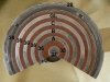
III- The stabilizer
A ring shaped pressed steel stabilizer (P06-27 ) is placed around the base of the rear motor. It centers and guides the rocket when placed in the RBU6000 launcher. It also stabilizes the rocket during flight in the air and travelling through water.
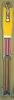
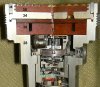
IV- Description and functioning of the UDV-60 (P07 ) electro mechanical time and impact fuze;
General info UDW60 fuze:
-length of fuze: 361 mm
-largest diameter of fuze: 135 mm
-stem diameter of the fuze: 74mm
-Weight of the fuze: 6,5 kg
Description of the UDW60 fuze (P07, P08, P10, P11, P12, P13, P14 ) :
The fuze is composed -from top to bottom- from the following main parts:
A – The fuze housing (P08, P09, P11, P13);
The fuze housing (P08, P09-28 ) consists of a cast and machined aluminium top housing. In the base of this housing, a threaded steel connection ring(P11-29 ) is screwed to receive the aluminium lower fuze housing (P11-30 ).
A small round window(P09-31 ) is placed in the side of the wide part of the fuze housing, allowing to read the fuze setting in seconds on the dial ring (P09-32 ).
The lower fuze housing (P11, P13-30 ) is internally threaded in top and base. In top it is screwed over the threaded connection ring (P11-29 ) at the base of the top part of the fuze housing, in the base the booster (P13-33 ) is screwed in.
B - The contact housing (P08, P09 );
The contact housing is an aluminium flange (P09-34 ) in which a bakelite housing (P09-35 ) is placed into which four brass rings (P08, P09-36 ) and a brass central pin (P08, P09-37 ) are fixated. The aluminium flange is fixated by a threaded ring (P08, P09-38 ). Below that, another bakelite flange (P09-39 ) is placed, used to house the wiring from the brass rings and the brass center pin. These wires are connected to the magnet of the gear locking device (P09-40 ) and the three magnets of the impulse motor.
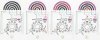
C – setting mechanism and time fuze (P09, P10 )
For the fuze setting, see added drawing ‘fuze setting motor’ (P10);
In this drawing black means no current, blue is current return (-), red (lightning bolt) means under current, purple is the current for the gear train lock. Yellow is the pole on the rotor pulled in line with the magnet. The numbers in green below point out the sequence.
The setting motor (P09-41 ) is composed of three magnets at 120 degrees each and a gear lock mechanism (P09-40 ) around a rotor wheel (P09-42 ) with an uneven number of poles. The three magnets form an even number division. The rotor has eleven and cannot form an even number division. Therefore, if one of three poles is in line with the a magnet, the other two are 1/3 before , and the other 1/3 past alignment with the other two magnets. This part forms the impulse motor.
The fuze setter (connected to the launcher) places five pins on four rings(P08-36 ) and the central brass pin (P08-37 ) on top of the fuze. When the outer ring is placed under current (purple) it activates a magnet that retracts a gear tooth shaped fixation pin (P09-43 ) from the top gearwheel (P09-44 ).
One of three magnets (P10) at 120 degrees each are placed under current in clockwise order (A,B,C, A,B,C) causing the rotor to rotate anticlockwise. As pole 01 is pulled to magnet A, pole 05 is partly aligned with magnet B. By taking the current of magnet A and placing current on magnet B, it is pulled aligned with magnet B. By this rotation pole 09 is now partly aligned with magnet C. By taking the current of magnet B and placing current on magnet C, it is pulled aligned with magnet C. By repeating this sequence the rotor will rotate, forcing the gearwheel on top of the stator to rotate with it. This gearwheel will rotate the dial ring and set the desired time.
The clockwork reduction geartrain (P09-45 ) and firing pin release mechanism (P09-46 ) below the setting motor is surprisingly similar to the German WW2 Zt.Z.30 mechanism; (why change a winning design?). The dial ring (P09-32 ) has a vertical rim on which the seconds time set are engraved, and it’s flange has a key shaped hole in the center to which a key (P09-47 ) below fits in only one position. The key is connected to the spring loaded reduction gear train (P09-45 ) that ends in an escapement mechanism (P09-48 ). The clockspring (P09-49 ) is placed inside the main gearwheel and is connected to the key directly. As soon as the gear train is released to run down (upon impact with waves) the key starts rotating, until the key fits the key hole in the base of the dial ring, and the key will be pushed upward by it’s spring, releasing the lever (P09-46 ) that prevents the firing pin from rotating. As soon as the firing pin (P09-50 ) rotates, it slips of the chamfered edge of a pin into the firing cap (P09-51 ).
Before full activation of the fuze (read; before hitting the waves), the gear train release mechanism (P09-52 ) keeps the gear train fixated.
D - The safety and activation mechanism (P11, P12 ):
The safety and activation mechanism prevents the time fuze geartrain (P09-45 ) and the impact fuze (P13, P14 ) from being activated prematurely upon launch. It also ensures the geartrain and impact fuze are released upon impact of the RGB60 rocket on water after launch only. The mechanism is composed of a cast and machined Zamac (an alloy of Zinc Aluminum Magnesium and Copper) mechanism housing (P11, P12-54 ), over which a inertia activated stepped bushing (P11, P12-54 ) is placed. It is kept in lower position by a spring (P11, P12,-55 ) above it, and fixated by a slider piece (P12-56 ). The mechanism housing has a central hole (P12-57 ), in which a small pipe of black powder (P12-58 ) is placed to boost the flame of the firing cap of the time fuze. A second hole (P12-59 ) is placed under an angle, starting at half the mechanism housing, ending on the circumference at the base.
The hole is kept interrupted by the slider (P12-56 ), which has an angular hole drilled (P12-60 ) that aligns with both top and angular hole when sliding into the armed position. The lower part of the central hole (P12-61 ) has a spring loaded inertia activated pin (P12-62 ) inserted that locks into a slot in the base of the slider (P12- 56). The hole for the pin is closed with a screw (P12-63 ).
Three further holes are drilled off centre into the length direction of the mechanism housing, two in top and one in the base.
-The first hole in top houses the initial ignition pellet (P11-64 ). Below this pellet, a spring loaded fixation pin (P11-65 ) is placed which is fixated in it’s lower position by a pressed black powder pellet (P11-66 ). Upon ignition of the rocket motor, the ignition pellet is activated, igniting the black powder pellet. When this has burned away, the spring loaded fixation pin moves upward, releasing the slider (P11, P12-56 ).
-The second hole houses the spring loaded fixation pin (P12-62 ) for the clockwork geartrain, kept fixated in upper position by a steel ball (P12-67 ) in the side. This ball is fixated inward by the stepped bushing (P11, P12-54 ). When the stepped bushing moves forward (upon impact with water), the ball is released to move outward, allowing the clockwork geartrain fixation pin to move down, releasing the clockwork geartrain to run down.
-The third hole is drilled in the base and houses a spring loaded firing cap (P12-68 ) in a firing cap housing (P12-69 ). This firing cap housing is fixated by a ball (P12-70 ) in the side. This ball is fixated inward by the stepped bushing (P11, P12-54 ). When the stepped bushing moves forward (upon impact with the water) the ball is released to move outward, releasing the firing cap to move into the firing pin (P12-71 ). The flame moves downward through the firing cap housing, into the black powder pyrotechnic safety mechanism (P12, P13, P14-72 ) of the impact fuze (P13, P14) below.
-A spring loaded radial pin -not visible in this cutaway model- is placed in a hole in the mechanism housing, just over the maximum stroke of the stepped bushing. If the stepped bushing moves forward, the pin moves outward, fixating the stepped bushing in it’s forward position.
E – The impact fuze (P13, P14) :
The impact fuze is placed in a cast and machined Zamac housing (P13-73 ). It has a central hole, and a big radial drilled hole in the middle (P14-74 ), which houses the all-ways fuze (P14-75 ). On top of the impact fuze housing, a radial slot is machined from the center to the circumference. In it, a strip of pressed black powder (P14-72 ) is placed. This black powder strip is ignited in the middle by the firing cap (P12-68 ) of the safety and activation mechanism above it, and burns both ways.
Burning to the center, it ignites a pressed black powder pellet (P14-76 ) which fixates a spring loaded pin (P14-77 ) in it’s lower position. When the pellet is burned away, the pin rises.
Burning to the circumference, it ignites a black powder pellet (P13-78 ) that shoots a flame downward through a drilled channel (P13-79 ) into a pressed black powder pellet(P13-80 ) in the lower part of the fuze housing. This pellet fixates a spring loaded pin (P13-81 ) into it’s lower position. When the pellet burns away, the pin rises. This pin fixates the spring loaded detonator slider(P13-82 ) which houses the heat sensitive detonator(P13-83 ) and a fixating pin (P13-84 ) on top of the slider. This pin fixates a springloaded flanged pipe piece (P13-85 ) that moves down as soon as the detonator slider moves to the armed position.
The big radial hole (P13, P14-74 ) houses two threaded caps (P14-86 ), which are machined conical shaped on the inside. Between these caps, two mushroom shaped slider pieces are fit together in a mirrored position. The stem of the slider piece (P14-87 ) that fits over the stem of the other (P14-88 ), locks up two balls (P14-89 ) that keep a spring loaded firing pin (P14-91 ) fixated. Just behind the balls, a groove (P14-90 ) is machined. When the two ‘mushroom sliders’ are telescoped inward, the balls are pressed outward into the groove by the spring loaded firing pin, releasing the firing pin (P14-91 ) to move into the firing cap (P14-92 ). The flame of the firing cap moves down into the heat sensitive detonator in the slider through the flanged pipe, igniting the booster charge (P13-33 ).
When the spring loaded safety pin and the flanged pipe piece are in locked position, the mushroom sliders cannot move inward, as soon as they are removed the fuze changes into a sensitive all-ways fuze, as there is not even a weak spring to keep the two slider halves apart.
At the base of the fuze housing, a closing cap (P13-93 ) is placed, kept in position by a threaded ring. (P13-94 ).
F- The booster charge :
The booster charge (P13-33 ) is screwed to the base of the fuze. It ignites the main charge of the depth charge.
Functioning of the RGB60 rocket upon firing:
- Before firing the rocket, the burya fire control system continuously calculates and adjusts the time setting of the clockwork mechanism. As the sinking rate of the rocket is constant (11,5 mtrs/sec), the detonation depth = 11,5 x seconds delay.
-Upon the moment of firing the following events take place: After the fire control system descides to use the long range motor (1500-5500 mtrs), either the short range (350-1500 mtrs) motor, one of both is started. At that moment the fuze setter is still pressed upon the top of the fuze, continuously adjusting time setting until the moment the -forward moving- rocket pushes the fuze setter away. The current falls away and the magnet with the fixating pin blocks the geartrain of the time setting part of the clock.
The electric current for starting one of both rocket motors runs through one of the ignition cartridges (P06-17 ) of the motor, as well as through the electric ignition of the initial pyrotechnic safety (P11-64 ) in the fuze. The current flows back through the central pin of the fuze (P08, P09-37 ).
Functioning of the UDV-60 fuze:
-The pyrotechnic initial firing safety ignition pellet is ignited (P11-64 ), burning away the pellet (P11-66 ) of the spring loaded pin (P11-65 ) which rises. This partly releases the slider (P11-56 )
-The springloaded pin (P11-62 ) is moved backward by the inertia upon firing, completely releasing the slider.
-The spring of the slider pushes the slider to the left, aligning the interrupted flame channel (P12-60 ). This also releases the stepped bushing (P11-54 ), which is now only kept in backward position by it’s creeping spring (P11-55 ).
-Upon impact with the waves, inertia moves the stepped bushing forward, releasing both the firing cap (P11-68/69 ) - and the gear train (P11-52 ) fixation pins.
-the reduction geartrain (P09-45 ) starts running down until the set time is expired and the firing pin is released, igniting the firing cap.
At the same moment the geartrain is released, the black powder safety’s (P13-72/76/78/80 ) of the all-ways impact fuze burn away, retracting both pins (P14-77/85 ) from between the mushroom shaped halves of the all-ways fuze(P14-75 ). The detonator slider (P13-82 ) has moved to its armed position. The fuze is now fully armed and live.
There are three ways the fuze can be activated;
- the time fuze runs down and the set time expires, the firing cap is activated, the flame travels down into the detonator slider along the long red channel, being strengthened on it’s way down by tube shaped black powder pellets. A slot is machined into the top of the right side of the detonator slider to allow the flame to reach the detonator.
- The rocket hits a target. The inertia moves forward the two mushroom shaped sliders, forcing them to telescope inward and release the firing pin. The flame travels down the flanged pipe into the detonator.
- Bombs exploding nearby will violently shake the bomb in the water. The violent sideways inertia movement will telescope the two mushroom shaped sliders inward, releasing the firing pin. The flame travels down the flanged pipe into the detonator.
Another You Tube movies showing the RBU-6000 anti submarine rocket launcher in action;
https://www.youtube.com/watch?v=M33AslTPraY&list=PL6521EDCFB5293306
The RBU-6000 anti submarine system was/is used by the following navy’s:
Russia (Navy and coastguard),
Ukraine
Poland
Romania
Bulgaria
Azerbaijan
Lithuania
Serbia
Montenegro
former Yugoslav navy
former DDR navy
India
Indonesia
Vietnam
Libya
Syria
Algeria
Ethiopia
Cuba.
The small round window (P09-31) has the following function: If rockets are not fired, the time clock has to be reset to zero, the fuze has to be removed from the rocket, and the rocket has to be taken out of the launcher.
The window allows for visual inspection if the clock has been set to zero after removal.
By today’s standards the RGB60 rocket is obsolete. It has been replaced by a new type of missile; the 90R missile that homes in on submarines up to 1000mtrs. deep. This missile can also be used to engage torpedo’s and frogman.
The RGB-60 can be used for shore bombardments in case of an emergency, I suppose one has to set the time fuze for the shortest time available, as the impact fuze will not function upon the first impact with the ground.
The first known RGB-60’s fired in wartime were by the Yugoslav Kotor class frigate Pula on 14 November 1991, when several volleys of RGB-60’s were fired at Croatian 88mm coastal defense guns on the Adriatic island of Solta.
It is claimed the Indonesian navy used the RGB-60 against Aceh Rebels in 2000, however there is no evidence supporting this claim
As far as known, the RGB-60 has never been used for its primary purpose; hunting submarines.
Since the German reunification in 1990, with countries like Poland, Bulgaria, Romania and Lithuania joining NATO, it can be considered a Nato weapon as well.
Regards, DJH
Part list:
1: Rounded steel nose piece
2: Explosives vessel
3: Closing cap
4: Sheet metal fuze well
5: Explosive charge
6: Trotyl layer
7: Heat resistant plastic layer
8: Pipe piece forward motor
9: Flange connection piece
10: Powder sticks forward motor
11: Upper grid forward motor
12: Pipe piece welded to flange connection piece (9 )
13: Grid upper motor
14: Forward motor booster charge
15: Igniter forward motor
16: Wires
17: Electric contact plug
18: Venturi’s
19: Non return valve
20: Pipe rear motor
21: Venturi flange
22: Venturi hole
23: Gasket housing
24: Rear motor booster charge
25: Powder sticks rear motor
26: Grid rear motor
27: Stabilizer
----------------------------------------------------------------------------------------------
28: Upper fuze housing
29: Connection ring
30: Lower fuze housing
31: Round window
32: Dial ring
33: Booster
34: Aluminium flange
35: Bakelite housing
36: Brass contact rings (+)
37: Central pin (-)
38: Threaded ring
39: Lower bakelite flange
40: Gear lock device magnet
41: Setting motor housing
42: Rotor wheel
43: Locking pin gear lock device
44: Top gear wheel setting mechanism
45: Time fuze reduction geartrain
46: Firing pin release lever
47: Key
48: Escapement
49: Clock spring in main gearwheel
50: Firing pin (springloaded)
51: Firing cap
52: Gear train inertia release pin
53: Safety mechanism housing
54: Stepped bushing
55: Spring
56: Slider (spring loaded)
57: Central hole in safety housing
58: Pipe shaped black powder pellet (flame booster)
59: Angular hole
60: Angular hole in slider (56)
61: Lower part central hole
62: Spring loaded inertia activated blocking pin
63: Screw
64: Initial ignition pellet
65: Spring loaded fixation pin for slider
66: Black powder pellet
67: Steel Ball
68: Firing cap
69: Firing cap housing
70: Steel Ball
71: Firing pin
72: Black powder strip
73: Zamac housing impact fuze
74: Radial hole for all-ways fuze
75: All-ways fuze
76: Black powder pellet
77: Spring loaded fixation pin for all-ways fuze
78: Black powder pellet
79: Vertical channel
80: Black powder pellet
81: Spring loaded pin
82: Spring loaded detonator slider
83: Detonator
84: Vertical pin on top of slider (82)
85: Spring loaded flanged pipe, fixation pin all-ways fuze
86: Threaded caps , internally cone shaped
87: Slider ‘mushroom’ 1
88: Slider ‘mushroom’ 2
89: Steel balls
90: Groove
91: Firing pin
92: Firing cap
93: Closing cap
94: Threaded ring
(P01-2 ) = (Picture 01-partnumber 2 ).
(P01, P04-2 ) = (Picture 01, Picture 04 -partnumber 2 ).
(P10) = full picture 10
The easiest way to read this posting is by placing the pictures in a map on your desktop so you can easily browse up and down the pictures, and use a printed text.
------------------------------------------------------------------------------------------------------------------------------------------------------------------------------------
Cutaway model of a Russian Naval RGB60 rocket propelled depth charge (P01, P02 ).
The RGB60 rocket propelled depth charge is used to destroy submarines through salvo fire. It is fired from the RBU6000-Smerch2 depth charge launcher. It was developed by the Moscow institute of thermal technology.
The launcher is manufactured by the Zavod artillery plant No.9 in Russia.
The RBU6000-Smerch2 depth charge launcher was designed in 1960. A working model was ready in 1961, and the weapon was put into full Warshaw pact fleet service in 1964. It was mounted on a wide array of Warsaw-pact naval surface vessels.
The RBU-6000 consists of 12 launching pipes, placed in a horseshoe shaped array. Rockets can be fired in salvos of 1, 2, 4, 8 or 12 rounds rippled.
Reloading is automatic by the -below deck- UP60 storage and reloading system, which places the rockets in the launcher one by one. The magazine capacity of the UP60 storage system is either 72 or 90 rounds per RBU6000 launcher system.
https://www.youtube.com/watch?v=0EW196Ka2so (RBU-6000 firing the homing 90R missile)
Loading of the RBU-6000 system aboard the Russian Grisha class anti submarine corvette ‘Albatros’ can be observed in this You Tube movie from 3:12 min to 4:12 min.
https://www.youtube.com/watch?v=wd5jVBhSJfI
The Soviet navy estimated that with using this system, the time between first sonar contact of the target submarine and it’s destruction would be between 60-90 seconds, with a kill probability of 0.8 at the first salvo.
To understand the functioning of this rocket and the launcher system, one first has to understand the dynamics of the submarine hunt.
An enemy submarine is an object constantly moving in three dimensions; up and down, left and right, forward and afterward, with varying speed. The submarine hunter moves in two dimensions; forward and afterward, left and right, but separate from that it’s hull also moves in three directions over the waves when it rolls, pitches and sheers. As one will understand this makes aiming quite an art.
When shooting at the maximum range (5500 mtrs in 10 seconds flight time) at an enemy submarine at the RGB60’s deepest working depth of 500mtrs. (43,5 seconds with a sink rate of 11,5 mtrs/sec), one will have to make an educated guess at which coordinates to expect the enemy submarine 53,5 seconds later.
The RBU6000 launcher is remotely directed by the PUSB Burya fire control system, that plots the cource and speed of the enemy submarine by sonar contact, and calculates/predicts on which coordinates -compared to the hunter’s position and speed upon firing- to shoot, so the enemy submarine and the depth charges meet.
Apart from aiming at the target, the rolling, pitching and sheering of the ship have to be compensated for seperately.
One can see this rolling compensation movement in this You Tube movie: https://www.youtube.com/watch?v=sdIvoPbpeyE
On the front end of the launching pipe of the RBU6000 one can see the fuze setter. This electric setting tool is pressed on top of the UDW60 fuze (P07 ) and keeps setting the time until the moment of launch, when the rocket leaving the launching pipe flips it over in the outer position. This ensures continuous time setting up to the moment of launch.
General info RGB60 depth charge:
Caliber of the rocket : 212mm
Length of the rocket : 1830mm
Weight of the rocket : 113,5 kg
Weight of the explosive charge : 23,5 kg
Minimal range : 300 mtr.
Maximum range : 5500 mtr.
Working depth range : Minimum 10 mtrs, maximum 500 mtrs
Sinking rate in seawater (constant) : 11,5 mtrs/sec
The RGB60 rocket propelled depth charge is build up of the following main parts:
I - warhead
II - rocket motor
III - stabilizer
IV - time and impact fuze UDW60
I- The warhead (P03 ) ;
The warhead is composed of a heavy steel nosepiece (P03-1 ) with a rounded nose, to which the sheet metal vessel (P03-2 ) is welded to the base. The base of the vessel reduces in diameter to receive the closing cap (P03, P04-3 ). In the center of the nosepiece a threaded hole is machined to receive the UDW60 fuze. A sheet metal tube (P03-4 ) is welded to the base of the hole in the nosepiece to house the fuze.
The explosive charge (P03, P04-5 ) is cast in the warhead from the base, the last inch being a separate cast of Trotyl (P03, P04,-6 ). Below this layer of Trotyl a 3mm thick “Textylscheibe” (P03, P04-7 ) –synthetic heat resistant material- is placed, protecting the explosive charge from the radiation heat of the motor below when launched.
The closing cap is screwed over the base of the warhead. It is threaded also on the outside to receive the pipe piece of the forward motor (P03, P04-8 ).
II- The rocket motor (P04, P05, P06 );
The rocket motor is composed of two separate motors: the forward motor (P04 ) and the rear motor (P05, P06 ).
Both motors are connected by a connection piece (P05-9 ).
The forward motor (P04 ):
The forward motor is a piece of pipe (P03, P04-8 ) that is threaded on the inside in top and base. In top is screwed over the base cap of the warhead, at the base it is screwed over the connection piece. Seven powder sticks (P04, P05-10 ) -with one hole in the center- are placed in the forward motor, locked up by a steel grid (P03, P04-11 ) on top.
The connection piece is a pipe piece (P05, P06 -12 ) with a flange welded on top (P05-9 ) which is externally threaded at the top part of the flange to receive the pipe piece of the upper rocket motor, and internally threaded at the lower part of the flange to receive the pipe piece of the lower rocket motor.
In the base of the forward motor, -on top if the connection piece- the grid (P05-13 ) is placed. The grid also houses the black powder booster charge (P05-14 ). At the base of the grid, below the booster charge the electric ignition charge (P05-15 ) is placed. Its wires (P05, P06-16 ) run down the pipe of the connection piece and end in an electric connection plug (P06-17 ) in the venturi (P06-18 ) of the forward motor at the base of the rocket.
Two spring loaded non-return valves (P05-19 ) are placed in the flange of the connection piece, connecting the forward and rear motor in the direction forward –rearward.
This is done for the following reason: when firing the missile it should hit the waves at a near vertical angle to positively activate the fuze. When the maximum range is 5500 mtrs, it means the rocket needs a certain speed to get that far and land in the waves near vertical. At short range this means the rocket has a too high speed and will hit the waves near horizontal.
To solve this problem, the motor is divided in two stages, a short range motor (300-1500 mtrs), and a long range motor (1500-5500 mtrs).
When short range is required, only the rear motor is activated, inducing spin on the rocket when fired. The non return valves are pushed closed.
If the long range is required, the forward motor is ignited. The pressurized gasses of the forward motor push open the non return valve and ignite the rear motor. Both motors are now used.
The rear motor (P05, P06-20 ):
The rear motor is a pipe piece (P05 P06-20 ), externally threaded in top and internally threaded at the base. In top it is screwed in the connection piece (P05-9 ). In the base a flange (P06-21 ) is screwed with a circular array of 14 venturi holes (P06-22 ) drilled at a 5 degree angle to induce spin to stabilize the rocket in flight. In the center of the flange a hole is drilled to receive the pipe of the connection piece (P06-12 ). The venturi (P06-18 ) is screwed into the base of this pipe, which also serves as a gasket housing (P06-23 ) between the upper and lower motor. In top of the rear motor a ring shaped black powder booster charge(P05-24 ) (ring shaped yellow tin) is placed on top of the powder sticks (P05, P06-25 ). Two electric igniters (missing in this cutaway model) are placed in opposite venturi holes in the venturi array of the base plate; they ignite the rear motor. A flame is blown through the center hole in the powder stick above the igniter, ending in the ring shaped black powder booster (P05-24 ) which ignites the rear motor
Eight powder sticks -with a hole in the center- are placed in the rear motor, around the pipe (P05, P06-12 ) of the connection piece. A grid (P06-26 ) is placed between the powder stick and the venturi’s to prevent pieces of burning powder sticks to obstruct the venture hole.
III- The stabilizer
A ring shaped pressed steel stabilizer (P06-27 ) is placed around the base of the rear motor. It centers and guides the rocket when placed in the RBU6000 launcher. It also stabilizes the rocket during flight in the air and travelling through water.
IV- Description and functioning of the UDV-60 (P07 ) electro mechanical time and impact fuze;
General info UDW60 fuze:
-length of fuze: 361 mm
-largest diameter of fuze: 135 mm
-stem diameter of the fuze: 74mm
-Weight of the fuze: 6,5 kg
Description of the UDW60 fuze (P07, P08, P10, P11, P12, P13, P14 ) :
The fuze is composed -from top to bottom- from the following main parts:
A – The fuze housing (P08, P09, P11, P13);
The fuze housing (P08, P09-28 ) consists of a cast and machined aluminium top housing. In the base of this housing, a threaded steel connection ring(P11-29 ) is screwed to receive the aluminium lower fuze housing (P11-30 ).
A small round window(P09-31 ) is placed in the side of the wide part of the fuze housing, allowing to read the fuze setting in seconds on the dial ring (P09-32 ).
The lower fuze housing (P11, P13-30 ) is internally threaded in top and base. In top it is screwed over the threaded connection ring (P11-29 ) at the base of the top part of the fuze housing, in the base the booster (P13-33 ) is screwed in.
B - The contact housing (P08, P09 );
The contact housing is an aluminium flange (P09-34 ) in which a bakelite housing (P09-35 ) is placed into which four brass rings (P08, P09-36 ) and a brass central pin (P08, P09-37 ) are fixated. The aluminium flange is fixated by a threaded ring (P08, P09-38 ). Below that, another bakelite flange (P09-39 ) is placed, used to house the wiring from the brass rings and the brass center pin. These wires are connected to the magnet of the gear locking device (P09-40 ) and the three magnets of the impulse motor.
C – setting mechanism and time fuze (P09, P10 )
For the fuze setting, see added drawing ‘fuze setting motor’ (P10);
In this drawing black means no current, blue is current return (-), red (lightning bolt) means under current, purple is the current for the gear train lock. Yellow is the pole on the rotor pulled in line with the magnet. The numbers in green below point out the sequence.
The setting motor (P09-41 ) is composed of three magnets at 120 degrees each and a gear lock mechanism (P09-40 ) around a rotor wheel (P09-42 ) with an uneven number of poles. The three magnets form an even number division. The rotor has eleven and cannot form an even number division. Therefore, if one of three poles is in line with the a magnet, the other two are 1/3 before , and the other 1/3 past alignment with the other two magnets. This part forms the impulse motor.
The fuze setter (connected to the launcher) places five pins on four rings(P08-36 ) and the central brass pin (P08-37 ) on top of the fuze. When the outer ring is placed under current (purple) it activates a magnet that retracts a gear tooth shaped fixation pin (P09-43 ) from the top gearwheel (P09-44 ).
One of three magnets (P10) at 120 degrees each are placed under current in clockwise order (A,B,C, A,B,C) causing the rotor to rotate anticlockwise. As pole 01 is pulled to magnet A, pole 05 is partly aligned with magnet B. By taking the current of magnet A and placing current on magnet B, it is pulled aligned with magnet B. By this rotation pole 09 is now partly aligned with magnet C. By taking the current of magnet B and placing current on magnet C, it is pulled aligned with magnet C. By repeating this sequence the rotor will rotate, forcing the gearwheel on top of the stator to rotate with it. This gearwheel will rotate the dial ring and set the desired time.
The clockwork reduction geartrain (P09-45 ) and firing pin release mechanism (P09-46 ) below the setting motor is surprisingly similar to the German WW2 Zt.Z.30 mechanism; (why change a winning design?). The dial ring (P09-32 ) has a vertical rim on which the seconds time set are engraved, and it’s flange has a key shaped hole in the center to which a key (P09-47 ) below fits in only one position. The key is connected to the spring loaded reduction gear train (P09-45 ) that ends in an escapement mechanism (P09-48 ). The clockspring (P09-49 ) is placed inside the main gearwheel and is connected to the key directly. As soon as the gear train is released to run down (upon impact with waves) the key starts rotating, until the key fits the key hole in the base of the dial ring, and the key will be pushed upward by it’s spring, releasing the lever (P09-46 ) that prevents the firing pin from rotating. As soon as the firing pin (P09-50 ) rotates, it slips of the chamfered edge of a pin into the firing cap (P09-51 ).
Before full activation of the fuze (read; before hitting the waves), the gear train release mechanism (P09-52 ) keeps the gear train fixated.
D - The safety and activation mechanism (P11, P12 ):
The safety and activation mechanism prevents the time fuze geartrain (P09-45 ) and the impact fuze (P13, P14 ) from being activated prematurely upon launch. It also ensures the geartrain and impact fuze are released upon impact of the RGB60 rocket on water after launch only. The mechanism is composed of a cast and machined Zamac (an alloy of Zinc Aluminum Magnesium and Copper) mechanism housing (P11, P12-54 ), over which a inertia activated stepped bushing (P11, P12-54 ) is placed. It is kept in lower position by a spring (P11, P12,-55 ) above it, and fixated by a slider piece (P12-56 ). The mechanism housing has a central hole (P12-57 ), in which a small pipe of black powder (P12-58 ) is placed to boost the flame of the firing cap of the time fuze. A second hole (P12-59 ) is placed under an angle, starting at half the mechanism housing, ending on the circumference at the base.
The hole is kept interrupted by the slider (P12-56 ), which has an angular hole drilled (P12-60 ) that aligns with both top and angular hole when sliding into the armed position. The lower part of the central hole (P12-61 ) has a spring loaded inertia activated pin (P12-62 ) inserted that locks into a slot in the base of the slider (P12- 56). The hole for the pin is closed with a screw (P12-63 ).
Three further holes are drilled off centre into the length direction of the mechanism housing, two in top and one in the base.
-The first hole in top houses the initial ignition pellet (P11-64 ). Below this pellet, a spring loaded fixation pin (P11-65 ) is placed which is fixated in it’s lower position by a pressed black powder pellet (P11-66 ). Upon ignition of the rocket motor, the ignition pellet is activated, igniting the black powder pellet. When this has burned away, the spring loaded fixation pin moves upward, releasing the slider (P11, P12-56 ).
-The second hole houses the spring loaded fixation pin (P12-62 ) for the clockwork geartrain, kept fixated in upper position by a steel ball (P12-67 ) in the side. This ball is fixated inward by the stepped bushing (P11, P12-54 ). When the stepped bushing moves forward (upon impact with water), the ball is released to move outward, allowing the clockwork geartrain fixation pin to move down, releasing the clockwork geartrain to run down.
-The third hole is drilled in the base and houses a spring loaded firing cap (P12-68 ) in a firing cap housing (P12-69 ). This firing cap housing is fixated by a ball (P12-70 ) in the side. This ball is fixated inward by the stepped bushing (P11, P12-54 ). When the stepped bushing moves forward (upon impact with the water) the ball is released to move outward, releasing the firing cap to move into the firing pin (P12-71 ). The flame moves downward through the firing cap housing, into the black powder pyrotechnic safety mechanism (P12, P13, P14-72 ) of the impact fuze (P13, P14) below.
-A spring loaded radial pin -not visible in this cutaway model- is placed in a hole in the mechanism housing, just over the maximum stroke of the stepped bushing. If the stepped bushing moves forward, the pin moves outward, fixating the stepped bushing in it’s forward position.
E – The impact fuze (P13, P14) :
The impact fuze is placed in a cast and machined Zamac housing (P13-73 ). It has a central hole, and a big radial drilled hole in the middle (P14-74 ), which houses the all-ways fuze (P14-75 ). On top of the impact fuze housing, a radial slot is machined from the center to the circumference. In it, a strip of pressed black powder (P14-72 ) is placed. This black powder strip is ignited in the middle by the firing cap (P12-68 ) of the safety and activation mechanism above it, and burns both ways.
Burning to the center, it ignites a pressed black powder pellet (P14-76 ) which fixates a spring loaded pin (P14-77 ) in it’s lower position. When the pellet is burned away, the pin rises.
Burning to the circumference, it ignites a black powder pellet (P13-78 ) that shoots a flame downward through a drilled channel (P13-79 ) into a pressed black powder pellet(P13-80 ) in the lower part of the fuze housing. This pellet fixates a spring loaded pin (P13-81 ) into it’s lower position. When the pellet burns away, the pin rises. This pin fixates the spring loaded detonator slider(P13-82 ) which houses the heat sensitive detonator(P13-83 ) and a fixating pin (P13-84 ) on top of the slider. This pin fixates a springloaded flanged pipe piece (P13-85 ) that moves down as soon as the detonator slider moves to the armed position.
The big radial hole (P13, P14-74 ) houses two threaded caps (P14-86 ), which are machined conical shaped on the inside. Between these caps, two mushroom shaped slider pieces are fit together in a mirrored position. The stem of the slider piece (P14-87 ) that fits over the stem of the other (P14-88 ), locks up two balls (P14-89 ) that keep a spring loaded firing pin (P14-91 ) fixated. Just behind the balls, a groove (P14-90 ) is machined. When the two ‘mushroom sliders’ are telescoped inward, the balls are pressed outward into the groove by the spring loaded firing pin, releasing the firing pin (P14-91 ) to move into the firing cap (P14-92 ). The flame of the firing cap moves down into the heat sensitive detonator in the slider through the flanged pipe, igniting the booster charge (P13-33 ).
When the spring loaded safety pin and the flanged pipe piece are in locked position, the mushroom sliders cannot move inward, as soon as they are removed the fuze changes into a sensitive all-ways fuze, as there is not even a weak spring to keep the two slider halves apart.
At the base of the fuze housing, a closing cap (P13-93 ) is placed, kept in position by a threaded ring. (P13-94 ).
F- The booster charge :
The booster charge (P13-33 ) is screwed to the base of the fuze. It ignites the main charge of the depth charge.
Functioning of the RGB60 rocket upon firing:
- Before firing the rocket, the burya fire control system continuously calculates and adjusts the time setting of the clockwork mechanism. As the sinking rate of the rocket is constant (11,5 mtrs/sec), the detonation depth = 11,5 x seconds delay.
-Upon the moment of firing the following events take place: After the fire control system descides to use the long range motor (1500-5500 mtrs), either the short range (350-1500 mtrs) motor, one of both is started. At that moment the fuze setter is still pressed upon the top of the fuze, continuously adjusting time setting until the moment the -forward moving- rocket pushes the fuze setter away. The current falls away and the magnet with the fixating pin blocks the geartrain of the time setting part of the clock.
The electric current for starting one of both rocket motors runs through one of the ignition cartridges (P06-17 ) of the motor, as well as through the electric ignition of the initial pyrotechnic safety (P11-64 ) in the fuze. The current flows back through the central pin of the fuze (P08, P09-37 ).
Functioning of the UDV-60 fuze:
-The pyrotechnic initial firing safety ignition pellet is ignited (P11-64 ), burning away the pellet (P11-66 ) of the spring loaded pin (P11-65 ) which rises. This partly releases the slider (P11-56 )
-The springloaded pin (P11-62 ) is moved backward by the inertia upon firing, completely releasing the slider.
-The spring of the slider pushes the slider to the left, aligning the interrupted flame channel (P12-60 ). This also releases the stepped bushing (P11-54 ), which is now only kept in backward position by it’s creeping spring (P11-55 ).
-Upon impact with the waves, inertia moves the stepped bushing forward, releasing both the firing cap (P11-68/69 ) - and the gear train (P11-52 ) fixation pins.
-the reduction geartrain (P09-45 ) starts running down until the set time is expired and the firing pin is released, igniting the firing cap.
At the same moment the geartrain is released, the black powder safety’s (P13-72/76/78/80 ) of the all-ways impact fuze burn away, retracting both pins (P14-77/85 ) from between the mushroom shaped halves of the all-ways fuze(P14-75 ). The detonator slider (P13-82 ) has moved to its armed position. The fuze is now fully armed and live.
There are three ways the fuze can be activated;
- the time fuze runs down and the set time expires, the firing cap is activated, the flame travels down into the detonator slider along the long red channel, being strengthened on it’s way down by tube shaped black powder pellets. A slot is machined into the top of the right side of the detonator slider to allow the flame to reach the detonator.
- The rocket hits a target. The inertia moves forward the two mushroom shaped sliders, forcing them to telescope inward and release the firing pin. The flame travels down the flanged pipe into the detonator.
- Bombs exploding nearby will violently shake the bomb in the water. The violent sideways inertia movement will telescope the two mushroom shaped sliders inward, releasing the firing pin. The flame travels down the flanged pipe into the detonator.
Another You Tube movies showing the RBU-6000 anti submarine rocket launcher in action;
https://www.youtube.com/watch?v=M33AslTPraY&list=PL6521EDCFB5293306
The RBU-6000 anti submarine system was/is used by the following navy’s:
Russia (Navy and coastguard),
Ukraine
Poland
Romania
Bulgaria
Azerbaijan
Lithuania
Serbia
Montenegro
former Yugoslav navy
former DDR navy
India
Indonesia
Vietnam
Libya
Syria
Algeria
Ethiopia
Cuba.
The small round window (P09-31) has the following function: If rockets are not fired, the time clock has to be reset to zero, the fuze has to be removed from the rocket, and the rocket has to be taken out of the launcher.
The window allows for visual inspection if the clock has been set to zero after removal.
By today’s standards the RGB60 rocket is obsolete. It has been replaced by a new type of missile; the 90R missile that homes in on submarines up to 1000mtrs. deep. This missile can also be used to engage torpedo’s and frogman.
The RGB-60 can be used for shore bombardments in case of an emergency, I suppose one has to set the time fuze for the shortest time available, as the impact fuze will not function upon the first impact with the ground.
The first known RGB-60’s fired in wartime were by the Yugoslav Kotor class frigate Pula on 14 November 1991, when several volleys of RGB-60’s were fired at Croatian 88mm coastal defense guns on the Adriatic island of Solta.
It is claimed the Indonesian navy used the RGB-60 against Aceh Rebels in 2000, however there is no evidence supporting this claim
As far as known, the RGB-60 has never been used for its primary purpose; hunting submarines.
Since the German reunification in 1990, with countries like Poland, Bulgaria, Romania and Lithuania joining NATO, it can be considered a Nato weapon as well.
Regards, DJH
Part list:
1: Rounded steel nose piece
2: Explosives vessel
3: Closing cap
4: Sheet metal fuze well
5: Explosive charge
6: Trotyl layer
7: Heat resistant plastic layer
8: Pipe piece forward motor
9: Flange connection piece
10: Powder sticks forward motor
11: Upper grid forward motor
12: Pipe piece welded to flange connection piece (9 )
13: Grid upper motor
14: Forward motor booster charge
15: Igniter forward motor
16: Wires
17: Electric contact plug
18: Venturi’s
19: Non return valve
20: Pipe rear motor
21: Venturi flange
22: Venturi hole
23: Gasket housing
24: Rear motor booster charge
25: Powder sticks rear motor
26: Grid rear motor
27: Stabilizer
----------------------------------------------------------------------------------------------
28: Upper fuze housing
29: Connection ring
30: Lower fuze housing
31: Round window
32: Dial ring
33: Booster
34: Aluminium flange
35: Bakelite housing
36: Brass contact rings (+)
37: Central pin (-)
38: Threaded ring
39: Lower bakelite flange
40: Gear lock device magnet
41: Setting motor housing
42: Rotor wheel
43: Locking pin gear lock device
44: Top gear wheel setting mechanism
45: Time fuze reduction geartrain
46: Firing pin release lever
47: Key
48: Escapement
49: Clock spring in main gearwheel
50: Firing pin (springloaded)
51: Firing cap
52: Gear train inertia release pin
53: Safety mechanism housing
54: Stepped bushing
55: Spring
56: Slider (spring loaded)
57: Central hole in safety housing
58: Pipe shaped black powder pellet (flame booster)
59: Angular hole
60: Angular hole in slider (56)
61: Lower part central hole
62: Spring loaded inertia activated blocking pin
63: Screw
64: Initial ignition pellet
65: Spring loaded fixation pin for slider
66: Black powder pellet
67: Steel Ball
68: Firing cap
69: Firing cap housing
70: Steel Ball
71: Firing pin
72: Black powder strip
73: Zamac housing impact fuze
74: Radial hole for all-ways fuze
75: All-ways fuze
76: Black powder pellet
77: Spring loaded fixation pin for all-ways fuze
78: Black powder pellet
79: Vertical channel
80: Black powder pellet
81: Spring loaded pin
82: Spring loaded detonator slider
83: Detonator
84: Vertical pin on top of slider (82)
85: Spring loaded flanged pipe, fixation pin all-ways fuze
86: Threaded caps , internally cone shaped
87: Slider ‘mushroom’ 1
88: Slider ‘mushroom’ 2
89: Steel balls
90: Groove
91: Firing pin
92: Firing cap
93: Closing cap
94: Threaded ring
Attachments
-
 P01 - Wasserbombe RGB60 cutaway model complete.JPG148.1 KB · Views: 62
 -
 P02 - Wasserbombe RGB60 backside cutaway model.JPG117.2 KB · Views: 55
 -
 P03 - Wasserbombe RGB60 cutaway warhead.JPG191 KB · Views: 53
 -
 P04 - Wasserbombe RGB60 cutaway forward motor.JPG224.4 KB · Views: 47
 -
 P05 - Wasserbombe RGB60 cutaway connection piece.JPG247.2 KB · Views: 51
 -
 P06 - Wasserbombe RGB60 cutaway stabilizer.jpg296.3 KB · Views: 45
 -
 P07 - UDW60 electromechanical time and impact fuze cutaway model.jpg292.4 KB · Views: 49
 -
 P08 - UDW60 Electromechanical time and impact fuze topview.JPG97.2 KB · Views: 45
 -
 P09 - UDW60 electromechanical time and impact fuze fuze setting -upper - part.JPG281.2 KB · Views: 45
 -
 P10 - drawing UDW60 electro mechanical time and impact fuze, time setting mechanism.jpg192.2 KB · Views: 45