I went to an airshow over the weekend, luckily not the Reno Air Races. The Airbase I visited hosts F-15E Strike Eagles from USAF and the Royal Singapore Air Force. I took a lot of photos of bombs and missiles which I will be posting as I get them organized. Unfortunately, everything was assembled using dummy and training assemblies, so there will be some discrepencies between the posted photos, and live ordnance.
Since you don't see any good photos on the net of how to build a Sidewinder M Model, I took some photos of various pieces/parts of the dummy missiles on the rails of the F-15Es.
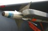
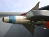
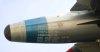
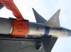
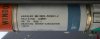
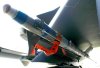
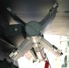
To build a missile, starting from the front you find the GCU (Guidance Control Unit) photos 1, 2, and 4, which is followd by the Target Detector (Proximity) which is covered with the orange protective wrap, the Warhead, and finally the motor. I didn't photograph the rear wings in detail, as Lou has already posted excellent photos of his set of 4. These 4 main body components are assembled using 3 clamps, which can be seen in photos 3, 5, 6, and 7. The components are keyed along with the clamps, so that all clamps are alligned on one side of the missile, opposite the side where the missile engages the mounting rails on the aircraft.
The fins on the GCU guide the missile towards the target. Small stainless steel cage brackets can be seen in photos 1 and 2, which keep these fins from moving, until the missile is launched. The Sidewinder is 5 inches in diameter.
All photos copyright HAZORD 2011.
Since you don't see any good photos on the net of how to build a Sidewinder M Model, I took some photos of various pieces/parts of the dummy missiles on the rails of the F-15Es.
To build a missile, starting from the front you find the GCU (Guidance Control Unit) photos 1, 2, and 4, which is followd by the Target Detector (Proximity) which is covered with the orange protective wrap, the Warhead, and finally the motor. I didn't photograph the rear wings in detail, as Lou has already posted excellent photos of his set of 4. These 4 main body components are assembled using 3 clamps, which can be seen in photos 3, 5, 6, and 7. The components are keyed along with the clamps, so that all clamps are alligned on one side of the missile, opposite the side where the missile engages the mounting rails on the aircraft.
The fins on the GCU guide the missile towards the target. Small stainless steel cage brackets can be seen in photos 1 and 2, which keep these fins from moving, until the missile is launched. The Sidewinder is 5 inches in diameter.
All photos copyright HAZORD 2011.
Attachments
-
 GCU 1.jpg97 KB · Views: 46
 -
 GCU 2.jpg96.4 KB · Views: 40
 -
 GCU Fuze WH and Motor.jpg97.6 KB · Views: 43
 -
 GCU Lettering.jpg97.5 KB · Views: 43
 -
 Fuze cover.jpg96.2 KB · Views: 42
 -
 Warhead.jpg95.1 KB · Views: 42
 -
 Motor lettering.jpg95.1 KB · Views: 37
 -
 Missile forward view.jpg94.3 KB · Views: 36
 -
 Missile Aft view.jpg96 KB · Views: 37
Last edited: