What's new
British Ordnance Collectors Network

This is a sample guest message. Register a free account today to become a member! Once signed in, you'll be able to participate on this site by adding your own topics and posts, as well as connect with other members through your own private inbox!

SS11 Aiming Box

StielGr

Well-Known Member
Hello and a Happy New Year to everyone.

This item was saved from being thrown in a skip so I thought I would share some pictures in the hope someone with good first hand knowledge would be able to explain how it worked.

I know it was used to target the NORD SS11 missile but were there other parts and what are the different switches and letter markings for?

I have tried to find pictures of the box in situe in the Scout helicopter but with no luck :tinysmile_cry_t:.

Any help would be much appreciated.

Many thanks
PC
 

Attachments

  • IMG_0837.jpg
    IMG_0837.jpg
    98 KB · Views: 68
  • IMG_0838.jpg
    IMG_0838.jpg
    96.1 KB · Views: 68
  • IMG_0839.jpg
    IMG_0839.jpg
    80.9 KB · Views: 56
  • IMG_0836.jpg
    IMG_0836.jpg
    73.5 KB · Views: 81
Very nice photos! Thanks for posting.

In addition to use on helicopters, the SS-11s could also be fired from ships, tanks, and from ground launchers. The local Nation Guard unit here in the states used them back in the 70s and 80s, firing from Helicopter launchers.
 
The box is known as a T10K Controller (don't ask me why T10K). The odd shaped knob in one corner is a clockwork controlled Rotary Firing Switch - the idea was that it controlled the missile firing and launch sequence, ie gyro run-up, flares ignition, rocket motor ignition. I used to talk about it when instructing on the missile, a lifetime ago. I don't know whether I still have much info on it. Before firing the switch would have to be pulled upwards and turned before release. I believe missile flight time was about 26 seconds but I may be wrong. I will have a dig in the attic and see whether I can get you more info. I used to know most of what you were asking.
 
Last edited:
Thank you for the words of appreciation Hazord.

I was starting to give up hope on this one Ammotech but your reply has been perfect. Many thanks for the information. Anything else would be excellent. Was there any other equipment for aiming or did the guy just follow the missile?

I had an idea the firing was controlled by the diamond shaped knob but with the gyro friction and pull up system it just seemed so slow to a press and fire trigger system. The whole process must have been nerve racking as you made a nice target all that time until impact.

What is the FF and VF switch and the P and Y light?

This box comes with a story but I have no way of authenticating it yet and unfortunately may never have.

PC
 
StielGr,

The SS-11 missile is wire guided, with 2 wires unspooling from it as it travels. The operator watches it and guides it with the joystick. It has two flares that burn on its tail end to make it easier for the operator to track it. It has 2 main rocket motor nozzels rear of the mid body, and a steering rocket gas tube that runs out the middle of the tail end. It is steered by four little fins that stick into the steering gas coming out the rear. Electromagnets move each fin left or right to deflect the gas one way or the other, pushing the missile to steer it.

The missile has at least 2 types of warheads, a TP/Practice one with orange dye packet, or the HEAT warhead. Interesting thing about the HEAT warhead, is that when it detonates, it extinguises the solid rocket motor, like blowing out a candle, and disentigrates the rocket. Large pieces of unburned propellant can be found on the battlefield, looking like hard rubber landmine shapes. One piece per missile.
 
I don't know if it's suitable info for here;
regards DJH

Anything about the SS11 is welcome so thank you for the link DJH.

Thank you again Hazord for the info about the guiding system. It must have taken a bit of skill if the firer just used his naked eye without any magnification system.

Does anyone know where the box was positioned in the Scout helicopter?

Thanks
PC
 
"It must have taken a bit of skill if the firer just used his naked eye without any magnification system"

That's why it's called a first generation missile. You needed a well trained gunner whom had a 80% chance of hitting a stationary target and 60 % on a moving target at the first shot.
You had to keep aim by looking through the sight and try to make your flare cover the target to enshure a hit.

The second generation are missiles like the spandrel, the TOW, the dragon etc., where you only have to keep your crosshairs on the target to enshure a hit. Even a minorly trained person is able hit a stationary target (90%) and a moving target (80%) with te first shot, as long as you keep your crosshairs on the target.

The third generation is fire and forget, missiles like the Javelin AT rocket , an instruction booklet will do to enshure even an untrained person can obtain a 100% hit. .
 
Last edited:
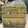
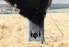
Hi StielGr, I found my course notes but not my photos yet. I believe the SS11 was a development of a WW2 German missile and was a little brother of another missile, the AS12. The first generation SS11 was superceded by the second generation Milan missile in UK service in the mid-late 1980s. The last users were Territorial Army squadrons of the Army Air Corps (see the handwritten info on your T10K). I remember doing initial acceptance inspections on about 300 of them in 1980 - 81. I believe they had recently arrived from the French manufacturer in Bourges. They were packed one to a box, six to a pallet in fibreglass boxes. The lid was an odd shape to accomodate the screw-on (Practice) warhead strapped in it (I believe HEAT warheads were separately packaged for UK use), with the MMA (missile main assemblage) in the lower half of the box and a small tool and missile history and record card kept in a small lidded compartment on the top of the lid. The manufacturer's film claimed `This missile is man-portable' as it showed a man carrying a boxed missile on his back as he climbed a mountain but at about 112 Lb (50 Kg?) that was stretching it. I believe one was used by Royal Marines in the ground role to score a direct hit on the conning tower of an Argentinian submarine when it surfaced off South Georgia in 1982 at the start of the Falklands conflict.

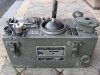
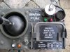
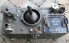
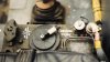
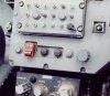
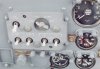
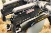
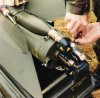
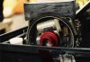
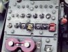
The T10K controller was otherwise known as the T10K generator. The box generated firing/launch commands and was used to control the missile in flight. It also provided a self test of its guidance signals (P & Y lamps) before firing. It had a 6 position rotary switch; a voltmeter for checking the aircraft power supply; a frequency selector switch (FF = fixed frequency, where the aircraft travels faster than 100 knots, VF = variable frequency, when the aircraft speed is 0 to 100 knots); red & green firing sequence indicator lamps (red when in progress, green when firing sequence complete); a 19 pole connector to the missile selector box and a 7 pole connector for training.

The firing and flight sequence went like this:
Minus 1 second - C position, where the air gunner has the rotary switch locked behind the ramp on the T10K - Missile locked on launcher, check Pitch & Yaw signals (the orange & white lamps).
The air gunner now lifts the rotary switch over the ramp and it continues under its clockwork mechanism.
0 seconds - O position - the latch release cartridge (the latch holds the missile in position on the launcher) fires, allowing the link rod to rise via a spring, to free the missile on the launcher and completes circuit connections.
0.15 second - IG position - Ignites the Gyro run-up charge (propellant contained within the rotor ball of the gyro), which burns for 0.15 second, to 40,000 RPM.
0.5 second - UG position - the gyro uncages (Uncage Gyro) and thermal batteries are ignited that provide the missile with in-flight power.
1 second - FB and F positions - Boost igniter and ball delay valve propellant fire (Fire Boost) and Flares are ignited. The missile launches. Note that the junction box remains on the launcher as missile/helicopter interface.
1.3 seconds - the sustain motor ignites, via the ball delay valves at front of the boost motor, 0.3 seconds into the flight.
2.2 seconds - The boost motor is burned out and the missile is fully controllable.
3.1 seconds - The fuze arms, 2.1 seconds into the flight.
21 seconds - The sustain motor is burned out, 20 seconds into the flight.
22 seconds plus - The wires are jettisoned at the junction box.
The tin-covered balsa wood wings were canted off by 0 degrees 48 minutes to give roll stability in flight. If a guidance wire broke the missile dived right.

The T10K was connected to the Missile Selector Box. The selector box was a vital part of the system, having an on/off switch, a missile selector switch, a master jettison switch (all missiles), a single jettison switch, a selection prohibition lamp (lit when a firing sequence was in progress) and a safety key as a master on/off switch. It was set up for firing missiles in the sequence Left outer (1), Right outer (2), Left inner (3) and Right inner (4).

The system also had a gyro stabilised sight - the AF110 - with three settings:
1 - Normal.
2 - x 2.5.
3 - x 10.

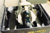
Flight time to maximum range of 3000 metres was about 20 seconds, not 26 as I wrote earlier (that was Swingfire). Minimum range was stated to be 400 metres (after 2.1 seconds of flight). Terminal speed was about 420 MPH. Penetration was stated to be up to two feet (60 cm) of armour plate. Flares (two per missile) were pre-fitted to operational missiles. A fuze protective cover also had to be removed before assembly of the missile. Each missile came with two thermal batteries that on assembly of the missile, were fitted to the forward end of the MMA, where they were held in position by spring clips. The warhead (HEAT 140 AC 62 B or Practice 125 59 S) was then screwed onto the MMA. There was also a Drill version. I don't know the meaning of the practice warhead info but for the HEAT, AC = Anti-Char (Anti-Tank), 140 = diameter of the cone in mm, and 62 B = year of design and suffix letter. The HEAT warhead was fitted with a Burdan anti-ricochet ring to help it grip a target at a low angle of attack. I believe it was milled, similar to the edge of eg a 10 p coin.

The boost and sustain rocket motors were of solid propellant in separate chambers, the boost behind the sustain. The `Simplet' boost motor had two side-mounted exhausts. Each had a carbon throat insert (venturi) and was closed with a melinex disc atmospheric seal. The boost motor comprised 3.6 Lb (1.6 Kg) of seven sticks of slotted tubular `Epictete E8' propellant, all burned after 1.2 seconds. Two ball delay valves were sited at the forward end of the boost motor section. Each contained propellant that was ignited at the same time as the boost motor and they burned for 0.3 of a second. After 0.3 second propellant gases from the boost motor passed through the ball delay valves to ignite the rear end of the `Sophie' sustain motor. The sustain motor was a single grain of 8.8 Lb (4 Kg) of E8 propellant with a burn time of about 19 seconds. Set into the sustain motor were three copper tubes. Their ends were exposed 1.8 seconds after sustain ignition, ie 2.1 seconds after launch (safety for the helicopter and crew in the event of premature detonation) and sustain motor gas pressure was bled off along them to arm the fuze. As Hazord has said, the sustain thrust exhausted through a central tube and missile directional control was via two pairs of jet deflectors, operated by electromagnets. All were in the eflux but when a pair was energised, one deflector would be pulled more into the eflux while its partner was correspondingly moved the same distance out of the eflux.

I will try to find my photos - they show positioning of the T10K & missile selector box etc.
 
Last edited:
Ammotechxt,

Thanks for all the info about the operation of the SS11! I have two questions. What happened if the selector switch was set to "Master Jettison"? What type of explosive was used in the HEAT warhead? It seems a bit excessive for a 140mm diameter copper cone to get 24 inches of penetration in armor.
 
Hello Hazord,

Pylons mounted on each side of the helicopter each supported two missile launchers, a total of four launchers and therefore four missiles per helicopter. As a safety feature, each launcher was fitted with an explosive jettison bolt, one supplied with each missile.

Operation of the master jettison switch would result in all four jettison bolts firing, to separate all four launchers and any attached missiles from the aircraft.

With regard to penetration I have no idea whether such a warhead and its charge could penetrate two feet of armour, or if so what type of armour, it is info that was given us by the Army School of Ammo.

With regard to the warhead filling I'm sorry but I don't think it is something I should put here.
 
Last edited:
As far as I know two types of explosives were used. The older type HEAT charge (as also used in the Antac missile) used comp B (mixture of hexogen and TNT), the later type used Hexal (hexogen with a few % aluminium.
 
Hi StielGr, I found my course notes .....................................................................I will try to find my photos - they show positioning of the T10K & missile selector box etc.

Wow......that is way more information than I ever dreamed of. I am extremely grateful that you took so much time to document all the details and post it up for me.

As I was reading through your notes I was able to follow all the different references and see how the sequence of events worked. The notes are very well written so I can tell that you were very good at your past job.

If you can find the pictures that would just be the icing on the cake.

Many thanks again.
PC
 
SS11 missile fired from Scout helicopter

Found my photos at last and scanned them this morning. I hope they will be of interest. Stiehlgr please show them to your friends - they may be able to identify exactly where in the cabin the controls were and tell you what the `unknown' column is. I will have to place the remaining photos on another one or two posts - too many for this one.
 

Attachments

  • Pallet of four boxed missiles, heads are stowed in the lids.jpg
    Pallet of four boxed missiles, heads are stowed in the lids.jpg
    93.1 KB · Views: 33
  • T10K controller (generates & controls SS11 firing sequence & missile in flight).jpg
    T10K controller (generates & controls SS11 firing sequence & missile in flight).jpg
    96.4 KB · Views: 34
  • Flare arming panel (Nitesun equipped Scout).jpg
    Flare arming panel (Nitesun equipped Scout).jpg
    80.2 KB · Views: 30
  • Unknown control in Nitesun equipped Scout.jpg
    Unknown control in Nitesun equipped Scout.jpg
    29.6 KB · Views: 29
  • Missile selector box.jpg
    Missile selector box.jpg
    71.9 KB · Views: 30
  • Dummy latch release cartridge fitted to launcher.jpg
    Dummy latch release cartridge fitted to launcher.jpg
    68 KB · Views: 34
  • Sockets for connection of rear end of missile.jpg
    Sockets for connection of rear end of missile.jpg
    47.9 KB · Views: 29
  • View into top of launcher - pylon.jpg
    View into top of launcher - pylon.jpg
    83.5 KB · Views: 30
  • Scout (Nitesun equipped version).jpg
    Scout (Nitesun equipped version).jpg
    50.3 KB · Views: 34
  • Armament selector panel.jpg
    Armament selector panel.jpg
    75.2 KB · Views: 32
SS11 Part Deux

More photos. Re the last set - I think I was wrong in saying there were six boxes to a pallet - there were just four in the photo. The first photo below shows a (cylindircal) thermal battery fitted over the fuze protector. This was an update to the previous missiles where two batteries were clipped in place. Where previously I said I believed they were thermal batteries, I think now that they may have been alkaline type batteries, giving rise to shelf life and reliability problems, hence the change to a single thermal battery.
 

Attachments

  • Missile ready area, taped off.jpg
    Missile ready area, taped off.jpg
    85.9 KB · Views: 36
  • Remains of sustain motors, each had 3 equi-spaced copper tubes set in the motor inhibitor, for a.jpg
    Remains of sustain motors, each had 3 equi-spaced copper tubes set in the motor inhibitor, for a.jpg
    100.6 KB · Views: 34
  • Scout with SS11.jpg
    Scout with SS11.jpg
    29.5 KB · Views: 30
  • Missiles loaded to left stations with latch release cartridges fitted above, associated with the.jpg
    Missiles loaded to left stations with latch release cartridges fitted above, associated with the.jpg
    95.6 KB · Views: 37
  • Fitting a latch release cartridge.jpg
    Fitting a latch release cartridge.jpg
    94.6 KB · Views: 33
  • SS11 on right outer station.jpg
    SS11 on right outer station.jpg
    95.9 KB · Views: 33
  • Missile on left inner launcher-pylon, left outer SS11 on ground behind.jpg
    Missile on left inner launcher-pylon, left outer SS11 on ground behind.jpg
    99.3 KB · Views: 37
  • Fitting a flare, latch release cartridge at top left & RNAD Gosport `Tested' stencil at bottom r.jpg
    Fitting a flare, latch release cartridge at top left & RNAD Gosport `Tested' stencil at bottom r.jpg
    88.7 KB · Views: 41
  • Rear end of missile - yellow traingle = junction box, brown under it = melinex disc waterproofin.jpg
    Rear end of missile - yellow traingle = junction box, brown under it = melinex disc waterproofin.jpg
    93.7 KB · Views: 40
  • Forward end of MMA. Red = fuze protector (no fuze fitted to this practice missile), round item a.jpg
    Forward end of MMA. Red = fuze protector (no fuze fitted to this practice missile), round item a.jpg
    93.9 KB · Views: 37
Last edited:
SS11 Part trois

Photo showing the missile master jettison switch.
 

Attachments

  • Master missile jettison switch = yellow & black stripes.jpg
    Master missile jettison switch = yellow & black stripes.jpg
    92.7 KB · Views: 21
Found my photos at last and scanned them this morning. I hope they will be of interest......

This is amazing.......but the picture you have posted of the T10K controller is the same controller that I have now.....unbelievable.
You can see it is marked:

SEM/SCOUT
041/ACC

I know little about this subject but it was strange that the "Armament selector panel" was fixed on the main cockpit display.
Would that not make it difficult for any future weapons upgrades?


Many thanks once again
 

Attachments

  • IMG_0838.jpg
    IMG_0838.jpg
    96.1 KB · Views: 10
Re the armament selector panel - I don't know. Best answer would come from aircrew or maintenance people.
 
Top