As this posting contains a lot of pictures accompanying the text, pictures and partnumbers are described in the following way:
(P01-2 ) = (Picture 01-partnumber 2 ).
(P01, P04-2 ) = (Picture 01, Picture 04 -partnumber 2 ).
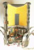
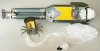
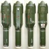
Cutaway models (P03 ) of the SG-357 runway penetrator bomb and the HB-876 air delivered -self erecting- area deniel mine, both used in the JP-233 -dispenser- weapon system. It was originally named the LAAAS (Low-Altitude Airfield Attack System), but this name was discontinued in favour of JP-233.
The JP-233 weapon system:
The JP-233 weapon system was developed in the late 1970’s by Hunting engineering / Royal Ordnance facory’s for low level high speed runway attacks on warshaw pact airfields in event of the cold war becomming hot.
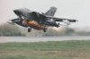
One of the problems in the late 1970’s was that guided missile air defence had improved to such a degree that high altitude attacks were becomming extremely dangerous, especially on heavily defended key assets like airfileds. Therefore one started to investigate the possibillities of low level high speed attacks, as an aircraft attacking with high speed on a low level appears and disappers too fast to take a good aim at, and SAM missiles and MANPADS were not really good at low altitudes (ground clutter) in the late 1970’s. Until 1977 it was a cooperative program with the US Air force, which wanted the weapon system to be used with the FB-111 low level strike plane. Improvements in terrain following radars which made safe high speed low level flying operations possible speeded up this development. However, due to rising costs the US air force pulled out of the program in 1980. After that, the Brittish completed the development on their own for use with their new MRCA Tornado bomber/fighter. The JP-233 weapon system was also suitable for usage with the F-16 fighting falcon and the Harrier, however it was used only with the Tornado (P01 ).
The JP-233 weapon system was taken into use with the RAF in 1987 and is sold to at least one other –unknown- customer. Several internet sources mention Saudi Arabia, although this cannot be confirmed.
The JP-233 weapon system exists of two -bolt connected- container modules with a streamlined nose and tail section. The forward section of the dispenser houses 215 pcs. HB-876 area deniel mines, the rearward section houses 30 pcs. SG-357 runway cratering bombs.
The complete length of the JP-233 dispenser is 21 foot and 6 “ long (6,55 mtrs), it is 840 mm wide and 600 mm high. The complete loaded weight is 2,335kg. ‘
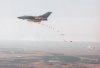
The weapon system was used in the following way; a MRCA Tornado was fitted with two JP-233 dispenser containers below the body, side by side. To attack the runway, the pilot flew over the centerline of a runway at appr. 153 mtrs (500 ft) mtrs. altitude. Upon activation of the JP-233 weapon system the dispenser began releasing SG-357 and HB-876 mines at preset intervals (P02). Both the bomb and the mine have a parachute /retarder that slows impact speed and descides the orientation in which the bomb or mine hits the ground.
The SG-357 runway cratering bomb blows (P04 & P05 ) a hole in the runway with it’s shaped charge, at the same time punching an explosive charge (P15 ) below the tarmac which detonates with short or long delay, forming camouflets below the runway upon detonation. A camouflet is an underground (most roundish) cavity –formed by an explosion – of which only a small entry hole and a heave of the runway tarmac are visable for a ground observer. Camoulflets are much more difficult to repair than normal bomb craters, as they have to be broken open to their full diameter, as where a normal bomb crater can just be buldozered full with debris and tar (or concrete) flush coated (see the added PDF drawing “JP-233 runway cratering weapon system”). SG-357’s with a short delay explode 0,5 seconds after being punched below the tarmac, the ones with long delay detonate in between 2 to12 hours after being punched below the tarmac.
With the JP-233 weapon system two hundred and fifteen HB-876 self erecting area deniel mines are used in conjunction with the SG-357 bombs to prevent repair crews from approaching the runway. The mine explodes when physically disturbed. The mines are said to self destruct at random set times between several minutes after being activated up to 24 hours or more.
Both types of submunitions are ejected from their dispensers by gas pressure from electrically ignited cartridges.
Dispersion is also arranged so that the area deniel mines land after the cratering explosions have taken place, allowing them to be distributed amongst the craters and the rubble.
The 24 hours of runway deniel may not sound spectacular, but in modern warfare in these 24 hours one can gain full air superiorety when most enemy runways are temporary disabled and the enemy is not able to get his planes in the air. By then, most of the hardened airplane shelters / bunkers have been attacked and the planes in them destroyed, as the first gulf war clearly showed.
During the first gulf war one found out that many Iraqi airfields were extremely large, so several missions over one airfield would have to be flown to fully disrupt it. This problem was overcome by using the JP-233 mainly against the crossings points of runways and the the taxiing lanes in front of the hardened shelters, preventing the planes from leaving the shelters all together.
The JP-233 was only used once in active service in a conflict; in night attacks in the first days of the first Gulf war. Tornados were first deployed to Tabuk airbase (Saudi Arabia) on 8 October 1990. The detachment comprised approximately 24 crews and 15 aircraft, drawn from various squadrons and bases. RAF Tornados also went to the Muharraq and Dharan airbases. Operations commenced on the night of 16/17 January 1991, initially with JP-233 anti-runway weapons and then with conventional free-fall bombs. Over hundred attacks with JP-233’s were carried out in the first days of the first gulf war.
Upon deployment, one of the flaws of the weapon system became apparent; the light of the exploding SG-357 bombs was so bright that the delivering aircraft were clearly visable against the night sky.
Another disadvantage was that the Tornado had to fly straight and level at low altitude, while bombing, making it vurnarable.
The main disadvantage of the JP-233 weapon system is that it is a very specialized weapon system suitable for only a very limitid number of tasks. Beside the primary task of runway destruction and runway deniel it could be used against rail marshalling yards or supply depots. This limited usage window makes it an extremely expensive weapon in the economic sense.
During the gulf war disturbing press reports emerged indicating that six Tornado’s were shot down during delivery of the JP-233 weapon system by ground fire. These reports were wrong. In fact only one of the JP 233 Tornado missions was shot down, and that was three minutes after the attack had been completed. The other Tornado losses were incurred when lofting 'dumb' bombs on Iraqi air defence installations.
With the increasing availability of standoff attack munitions capable of the same mission with little risk to the flight crew and aircraft, and the British entry into the 1997 Land Mines Ban Treaty (which declares the HB-876 illegal), the JP-233 weapon system has been withdrawn from service in 1999.
A very interesting short movie from the Imperial War museum can be found here:
http://www.iwm.org.uk/collections/item/object/1060018963
When you use the search term “JP-233” on You-Tube, another interesting short movie can be found about the JP-233 weapon system:
http://www.youtube.com/watch?v=ZAGmDqH4c-8
The ‘BOMB, RUNWAY PENETRATOR, 26-KG, NO.1, MK.1 (SG-357)’; description and functioning:
In functioning, the SG-357 bomb is build up of an upper and a lower part.
The upper part houses the -primary- shaped charge that punches a hole in the runway. The lower part is the secondary charge that is punched below the runway by the residual energy of the shaped charge, to explode below the runway with or without delay.
Main parts description from top to bottom:
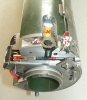
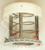
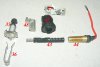
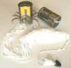
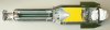
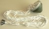
- (P06 ) The complete parachute assembly; Parachute, wires, and the aluminium parachute container.
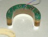
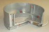
- (P07 ) The aluminium parachute wire anchor frame. This machined aluminium cast frame houses the parachute ejection cartridge (P07-1 ), the gas channels (P07-2 ) ending in two cylinders (P07-3 ), and the four attachment points for the parachute wires (P07-4 ). It also houses a small shaft that fixates an arming wire (P10, P20-5 )
- (P08 ) The parachute wire housing. This black plastic housing is connected to the aluminium parachute container by means of a number of crimps. Two pistons (P08-6 ) are placed on the outer circumference of the parachute wire housing that fit in the cylinders on the parachute wire anchor frame. The parachute wires are stored in this black plastic housing. They are folded to two bundles, held together by means of rubber bands
- (P09 ) The aluminium lock up ring (P09-7 ). This ring has four small shear pins – at 90 degr each- that keep the parachute wire anchor frame in it’s forward position. It also forms the endstop rim for the parachute wire ancor frame when this moves backward.
A thin fixation ring (P09-8 ) is placed around the lock up ring and the base of the parachute container. It is held in position by means of small crimps.
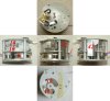
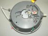
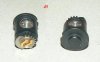
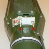
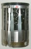
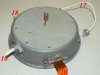
- (P10, P11, P12, P13 ) The zamac fuze housing (P10 ) with the mechanical S&A mechanism (P11 ) and the electronics ring (P12 ). In the center, a spring loaded (P11-9 ) reduction gear is placed (P11-10 ). Upon activation, the geartrain runs down, slowing the rotation the electric firing cap (P11-11) on a rotor (P11-12 ), from out of center into center –above the detonator (P09-13 ) -, as well as closing a slidercontact for the electric firing cap. A secondary - parrallel- geartrain (P11-14 ) rotates a gearwheel to which a brass strip is glued, closing another electric slider contact circuit, most probably to activate the secondary charge fuze.
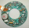
Around the mechanical S&A device in the fuze housing a ring of electronics is placed, cast in Pur foam. The big cilinder (P7-15 )on the electronics ring is the thermal battery. For the rest –as far as my little electronic knowledge goes- the electronics disc contains many transistors, resistances, two microchips, and some capacitors.
In the side of the fuze housing, an activation switch (P10, P18-16 ) is placed. With the bomb placed in the bomb rack of the dispenser, the activation switch is pushed inward. Upon release, the switch (P13-40 ) falls outward, closing the starting circuits, activating the bomb’s battery and electronics.
Three electric wires appear from- the fuze housing; the first one runs from the fuze housing to the parachute ejection cartridge (P10-17 ), the second wire (P10-18 ) runs from the connector plug (P27-19 ) at the end face of the aluminium block to the fuze housing. It is meant to start up the electronics just prior to bomb ejection.
The third –flat data cable(P10-20 ) - runs from the fuze of the primary charge to the fuze of the secondary charge (P16 ) .
In the center of the base plate (P13-21 ) of the fuze housing the detonator (P09-13 ) is placed, activated by the electric firing cap (P11-11 ) -when rotated in line-. Around this detonator, a steel deflector is (P09-23 ) placed, deflecting the force of the booster (P14 ) downward.
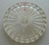
- (P14 ) The -transparant- plastic booster flange (P09-24 ) is placed below the fuze housing (P10 ). Twenty four radial channels (P14-25 ) , ending in 24 longitudal holes at the circumference of the flange (P14-26 ). In these holes detonator pellets (P09-27 ) are placed to enshure the detonation wave starts on the outside of the explosive charge instead of the center. Initiating the detonation in this way enshures the detonation wave will take the shape of the cone when moving downward, hitting the entire cone surface instantainously, instead of a linear movement from top to bottom over the cone when initited from the center. A 19mm high disc of explosives (P09-28 ) is glued to the base of the booster flange to enshure an uniform contact with the circumferencal booster pellets.
A felt washer ring (P09-29 ) is placed between the fuze housing and the booster flange.
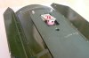
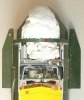
- (P05 ) The cone is a blunt (appr. 90 degr) aluminium cone. This means the -instantaniously formed- jet will be quite massive and short (with less penetrative power than a sharp pointed thin walled cone), but it will do a great job punching through the tarmac of a runway, punching a hole big enough to make the secondary charge disappear into the hole. The explosive charge behind the cone exists of 5,95 Kg RDX/HMX/TNT.
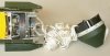
- (P04, P05 ) The aluminium bomb body. This is a soft aluminium body, tapered and threaded at the base to receive the secondary –cratering- charge. The body has four small fins that give the bomb direction after release. On one side a dove tail plate (P04-31 ) is screwed to the body to fixate the bomb in the sliding rail of the bomb rack. Below the end of the rail an aluminium block is screwed. To the end face of the block a connector plug is placed as well as two pointed positional fixation pins (P27-30) that enshure the connector plug (P27-19 ) fits closely at once.
On the opposite side of the bomb body an aluminium block with three machined slots (P04-32 ) is bolted to the body. I suppose this is the bomb release notch.
Arond the circumference of the bomb, three covered channels run down. The first one (P04-33 ) is a flat channel that houses a flat data cable, running from the fuze housing of the shaped charge to the fuze of the secondary charge. The second cable channel (P04-34 ) connects the plug on the face end (P27-19 ) with the fuze housing. The third one is a stainless steel pipe (P04-35 ), which runs from the top of the upper part to the fuze of the secondary charge. The pipe houses a steel cable that is bolted to the parachute wire anchor frame through a longitudal slot in the bomb body (P21 ). The other side of the wire is connected to a “peg” (P22-36 ) that keeps the locking pin (P22-37 ) from the secondary charge fuze locked in outward position.
- (P15 ) The secondary charge exists of a cylindrical body made from high tensile steel, with a steel pipe screwed in the center. Between these two pipes an explosive charge of 1,80 Kg RDX (gray) is cast.
The base of the outer pipe is theaded on the inside to receive the base fuze. A thick felt washer is placed between the fuze and the explosive charge.
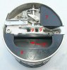
- (P16 ) The base fuze. This stainless steel fuze houses the mechanical S&A device. It also houses the cast in electronics (P26) locked up between two pur foam shock absorbers.
- (P17 ) The extandable impact sensor. During transport in the bomb rack the impact sensor is retracted.
After release of the bomb and activation of the fuze of the secondary charge, a ring (P25-38 fixating the impact sensor is rotated, releasing the impact sensor. The impact sensor has “fingers” (P17-39 ) at the base . When the bomb hits the ground, the “fingers” on the front of the sensor will close either an electric circuit, either activate a piezo electric crystal. I am not shure which, but one of both, and (sorry!)I am not willing to bend one open to see and damage a nice cutaway model.
Functioning of the SG-357 bomb:
The Bomb is placed in the dispenser with the parachute facing downward. Upon ejection , the bomb is electrically activated through the connector plug (P27-19 ) When the bomb slides down the dove tail plate upon ejection from the dispenser, the activation switch (P18-16 ) moves outward, closing the electric circuits (P13-40 ) in the fuze housing. The thermal battery starts delivering current and activates the parachute ejection cartridge (P07-1 ) after 0,5 seconds delay, enshuring a safe seperation distance from the delivering Tornado. The gasses of this cartridge start pushing the pistons outward, breaking the fixation ring and pushing the parachute wire housing and the parachute container away backward.
The wires stretch as the parachute container catches the wind and the ‘break away’ window (P08-41 ) in the parachute wire housing breaks away and the parachute is pulled out and released. This results in a huge pull to the parachute wire anchor frame. The frame moves backward (P19 (P20 ), breaking the four shear pins, being stopped only by the smaller diameter rim in the lock up ring. By moving backwards, the parachute wire anchor frame removes two safety’s -a pin (P20-5 ) and a “ safety peg”(P22-36 )- , and a setback-release weight (P11-42 )in the mechanical S&A mechanism that is also activated by the huge pull. The pin (P20-5 ) is withdrawn from the center of the mechanical S&A mechanism in the fuze housing, which allows the springloaded geartrain to run down, rotating the electric firing cap above the detonator (red) while at the same time the cable in the stainless steel pipe is pulled upward (P21 ), removing the “safety peg” from the locking pin of the secondary charge fuze. This locking pin (P22, P23-37 ), fixating the arming tooth rack (P23-43 ) moves outward, releasing the tooth rack. The electronics ring passes a signal to the explosive piston (P16-44 ) , which moves outward, moving the toothrack outward P16-43 ). This rotates the gear driven elecrically primed firing (P24-45 ) (P23-45) cap 90 degrees from short circuit to closed circuit, and from ‘out of line’ to ‘in line’ with the detonator pellet (P16-46 ). A small spring steel plate (P22-47 ) on the back face of the firing cap housing fits the shape of a notch on the outside of the firing cap. When rotated, it fits like lock and key, fixating the firing cap in it’s armed position. The toothrack also rotates a notch (P16, P23-48 ) that –on it’s turn- rotates a release ring (P25-38 ) that keeps the impact sensor inward by means of three small arrest hooks (P17-49 ). When the ring rotates, the hooks are released, allowing the spring to extend the impact sensor. Three legs unfold, fixated by means of spring loaded plastic filler pieces (P17-50 ). Meanwhile the electronics (P26 ) in the secondary charge have also been activated, enshuring a short, either a long delay. The bomb now falls down, retarded by the parachute, it’s trajectory changing from near horizonal to vertical. When the impact sensor hits the ground, an electric signal is send back to the electric firing cap of the shaped charge in top. The shaped charge explodes, passing the jet through the center pipe of the secondary charge, punching a deep hole through te runway, also punching the secondary charge below the runway. This also explains why the top part of the secondary charge is quite massive; it prevents spall from the shaped charge jet from detonating the secondary charge prematurely. The secondary charge will either explode after 0,5 seconds, either between 2 to12 hours.
Both the pictured complete (of course inert!) bomb as well as the cut and described bomb have a 0,5 seconds ‘short delay’.
Many thanks to Joop Dijkman from the MTM-DAWN museum in Landhorst for allowing me to picture his full inert but complete SG-357 bomb, and take it apart for detailed parts picturing.
(P01-2 ) = (Picture 01-partnumber 2 ).
(P01, P04-2 ) = (Picture 01, Picture 04 -partnumber 2 ).
Cutaway models (P03 ) of the SG-357 runway penetrator bomb and the HB-876 air delivered -self erecting- area deniel mine, both used in the JP-233 -dispenser- weapon system. It was originally named the LAAAS (Low-Altitude Airfield Attack System), but this name was discontinued in favour of JP-233.
The JP-233 weapon system:
The JP-233 weapon system was developed in the late 1970’s by Hunting engineering / Royal Ordnance facory’s for low level high speed runway attacks on warshaw pact airfields in event of the cold war becomming hot.
One of the problems in the late 1970’s was that guided missile air defence had improved to such a degree that high altitude attacks were becomming extremely dangerous, especially on heavily defended key assets like airfileds. Therefore one started to investigate the possibillities of low level high speed attacks, as an aircraft attacking with high speed on a low level appears and disappers too fast to take a good aim at, and SAM missiles and MANPADS were not really good at low altitudes (ground clutter) in the late 1970’s. Until 1977 it was a cooperative program with the US Air force, which wanted the weapon system to be used with the FB-111 low level strike plane. Improvements in terrain following radars which made safe high speed low level flying operations possible speeded up this development. However, due to rising costs the US air force pulled out of the program in 1980. After that, the Brittish completed the development on their own for use with their new MRCA Tornado bomber/fighter. The JP-233 weapon system was also suitable for usage with the F-16 fighting falcon and the Harrier, however it was used only with the Tornado (P01 ).
The JP-233 weapon system was taken into use with the RAF in 1987 and is sold to at least one other –unknown- customer. Several internet sources mention Saudi Arabia, although this cannot be confirmed.
The JP-233 weapon system exists of two -bolt connected- container modules with a streamlined nose and tail section. The forward section of the dispenser houses 215 pcs. HB-876 area deniel mines, the rearward section houses 30 pcs. SG-357 runway cratering bombs.
The complete length of the JP-233 dispenser is 21 foot and 6 “ long (6,55 mtrs), it is 840 mm wide and 600 mm high. The complete loaded weight is 2,335kg. ‘
The weapon system was used in the following way; a MRCA Tornado was fitted with two JP-233 dispenser containers below the body, side by side. To attack the runway, the pilot flew over the centerline of a runway at appr. 153 mtrs (500 ft) mtrs. altitude. Upon activation of the JP-233 weapon system the dispenser began releasing SG-357 and HB-876 mines at preset intervals (P02). Both the bomb and the mine have a parachute /retarder that slows impact speed and descides the orientation in which the bomb or mine hits the ground.
The SG-357 runway cratering bomb blows (P04 & P05 ) a hole in the runway with it’s shaped charge, at the same time punching an explosive charge (P15 ) below the tarmac which detonates with short or long delay, forming camouflets below the runway upon detonation. A camouflet is an underground (most roundish) cavity –formed by an explosion – of which only a small entry hole and a heave of the runway tarmac are visable for a ground observer. Camoulflets are much more difficult to repair than normal bomb craters, as they have to be broken open to their full diameter, as where a normal bomb crater can just be buldozered full with debris and tar (or concrete) flush coated (see the added PDF drawing “JP-233 runway cratering weapon system”). SG-357’s with a short delay explode 0,5 seconds after being punched below the tarmac, the ones with long delay detonate in between 2 to12 hours after being punched below the tarmac.
With the JP-233 weapon system two hundred and fifteen HB-876 self erecting area deniel mines are used in conjunction with the SG-357 bombs to prevent repair crews from approaching the runway. The mine explodes when physically disturbed. The mines are said to self destruct at random set times between several minutes after being activated up to 24 hours or more.
Both types of submunitions are ejected from their dispensers by gas pressure from electrically ignited cartridges.
Dispersion is also arranged so that the area deniel mines land after the cratering explosions have taken place, allowing them to be distributed amongst the craters and the rubble.
The 24 hours of runway deniel may not sound spectacular, but in modern warfare in these 24 hours one can gain full air superiorety when most enemy runways are temporary disabled and the enemy is not able to get his planes in the air. By then, most of the hardened airplane shelters / bunkers have been attacked and the planes in them destroyed, as the first gulf war clearly showed.
During the first gulf war one found out that many Iraqi airfields were extremely large, so several missions over one airfield would have to be flown to fully disrupt it. This problem was overcome by using the JP-233 mainly against the crossings points of runways and the the taxiing lanes in front of the hardened shelters, preventing the planes from leaving the shelters all together.
The JP-233 was only used once in active service in a conflict; in night attacks in the first days of the first Gulf war. Tornados were first deployed to Tabuk airbase (Saudi Arabia) on 8 October 1990. The detachment comprised approximately 24 crews and 15 aircraft, drawn from various squadrons and bases. RAF Tornados also went to the Muharraq and Dharan airbases. Operations commenced on the night of 16/17 January 1991, initially with JP-233 anti-runway weapons and then with conventional free-fall bombs. Over hundred attacks with JP-233’s were carried out in the first days of the first gulf war.
Upon deployment, one of the flaws of the weapon system became apparent; the light of the exploding SG-357 bombs was so bright that the delivering aircraft were clearly visable against the night sky.
Another disadvantage was that the Tornado had to fly straight and level at low altitude, while bombing, making it vurnarable.
The main disadvantage of the JP-233 weapon system is that it is a very specialized weapon system suitable for only a very limitid number of tasks. Beside the primary task of runway destruction and runway deniel it could be used against rail marshalling yards or supply depots. This limited usage window makes it an extremely expensive weapon in the economic sense.
During the gulf war disturbing press reports emerged indicating that six Tornado’s were shot down during delivery of the JP-233 weapon system by ground fire. These reports were wrong. In fact only one of the JP 233 Tornado missions was shot down, and that was three minutes after the attack had been completed. The other Tornado losses were incurred when lofting 'dumb' bombs on Iraqi air defence installations.
With the increasing availability of standoff attack munitions capable of the same mission with little risk to the flight crew and aircraft, and the British entry into the 1997 Land Mines Ban Treaty (which declares the HB-876 illegal), the JP-233 weapon system has been withdrawn from service in 1999.
A very interesting short movie from the Imperial War museum can be found here:
http://www.iwm.org.uk/collections/item/object/1060018963
When you use the search term “JP-233” on You-Tube, another interesting short movie can be found about the JP-233 weapon system:
http://www.youtube.com/watch?v=ZAGmDqH4c-8
The ‘BOMB, RUNWAY PENETRATOR, 26-KG, NO.1, MK.1 (SG-357)’; description and functioning:
In functioning, the SG-357 bomb is build up of an upper and a lower part.
The upper part houses the -primary- shaped charge that punches a hole in the runway. The lower part is the secondary charge that is punched below the runway by the residual energy of the shaped charge, to explode below the runway with or without delay.
Main parts description from top to bottom:
- (P06 ) The complete parachute assembly; Parachute, wires, and the aluminium parachute container.
- (P07 ) The aluminium parachute wire anchor frame. This machined aluminium cast frame houses the parachute ejection cartridge (P07-1 ), the gas channels (P07-2 ) ending in two cylinders (P07-3 ), and the four attachment points for the parachute wires (P07-4 ). It also houses a small shaft that fixates an arming wire (P10, P20-5 )
- (P08 ) The parachute wire housing. This black plastic housing is connected to the aluminium parachute container by means of a number of crimps. Two pistons (P08-6 ) are placed on the outer circumference of the parachute wire housing that fit in the cylinders on the parachute wire anchor frame. The parachute wires are stored in this black plastic housing. They are folded to two bundles, held together by means of rubber bands
- (P09 ) The aluminium lock up ring (P09-7 ). This ring has four small shear pins – at 90 degr each- that keep the parachute wire anchor frame in it’s forward position. It also forms the endstop rim for the parachute wire ancor frame when this moves backward.
A thin fixation ring (P09-8 ) is placed around the lock up ring and the base of the parachute container. It is held in position by means of small crimps.
- (P10, P11, P12, P13 ) The zamac fuze housing (P10 ) with the mechanical S&A mechanism (P11 ) and the electronics ring (P12 ). In the center, a spring loaded (P11-9 ) reduction gear is placed (P11-10 ). Upon activation, the geartrain runs down, slowing the rotation the electric firing cap (P11-11) on a rotor (P11-12 ), from out of center into center –above the detonator (P09-13 ) -, as well as closing a slidercontact for the electric firing cap. A secondary - parrallel- geartrain (P11-14 ) rotates a gearwheel to which a brass strip is glued, closing another electric slider contact circuit, most probably to activate the secondary charge fuze.
Around the mechanical S&A device in the fuze housing a ring of electronics is placed, cast in Pur foam. The big cilinder (P7-15 )on the electronics ring is the thermal battery. For the rest –as far as my little electronic knowledge goes- the electronics disc contains many transistors, resistances, two microchips, and some capacitors.
In the side of the fuze housing, an activation switch (P10, P18-16 ) is placed. With the bomb placed in the bomb rack of the dispenser, the activation switch is pushed inward. Upon release, the switch (P13-40 ) falls outward, closing the starting circuits, activating the bomb’s battery and electronics.
Three electric wires appear from- the fuze housing; the first one runs from the fuze housing to the parachute ejection cartridge (P10-17 ), the second wire (P10-18 ) runs from the connector plug (P27-19 ) at the end face of the aluminium block to the fuze housing. It is meant to start up the electronics just prior to bomb ejection.
The third –flat data cable(P10-20 ) - runs from the fuze of the primary charge to the fuze of the secondary charge (P16 ) .
In the center of the base plate (P13-21 ) of the fuze housing the detonator (P09-13 ) is placed, activated by the electric firing cap (P11-11 ) -when rotated in line-. Around this detonator, a steel deflector is (P09-23 ) placed, deflecting the force of the booster (P14 ) downward.
- (P14 ) The -transparant- plastic booster flange (P09-24 ) is placed below the fuze housing (P10 ). Twenty four radial channels (P14-25 ) , ending in 24 longitudal holes at the circumference of the flange (P14-26 ). In these holes detonator pellets (P09-27 ) are placed to enshure the detonation wave starts on the outside of the explosive charge instead of the center. Initiating the detonation in this way enshures the detonation wave will take the shape of the cone when moving downward, hitting the entire cone surface instantainously, instead of a linear movement from top to bottom over the cone when initited from the center. A 19mm high disc of explosives (P09-28 ) is glued to the base of the booster flange to enshure an uniform contact with the circumferencal booster pellets.
A felt washer ring (P09-29 ) is placed between the fuze housing and the booster flange.
- (P05 ) The cone is a blunt (appr. 90 degr) aluminium cone. This means the -instantaniously formed- jet will be quite massive and short (with less penetrative power than a sharp pointed thin walled cone), but it will do a great job punching through the tarmac of a runway, punching a hole big enough to make the secondary charge disappear into the hole. The explosive charge behind the cone exists of 5,95 Kg RDX/HMX/TNT.
- (P04, P05 ) The aluminium bomb body. This is a soft aluminium body, tapered and threaded at the base to receive the secondary –cratering- charge. The body has four small fins that give the bomb direction after release. On one side a dove tail plate (P04-31 ) is screwed to the body to fixate the bomb in the sliding rail of the bomb rack. Below the end of the rail an aluminium block is screwed. To the end face of the block a connector plug is placed as well as two pointed positional fixation pins (P27-30) that enshure the connector plug (P27-19 ) fits closely at once.
On the opposite side of the bomb body an aluminium block with three machined slots (P04-32 ) is bolted to the body. I suppose this is the bomb release notch.
Arond the circumference of the bomb, three covered channels run down. The first one (P04-33 ) is a flat channel that houses a flat data cable, running from the fuze housing of the shaped charge to the fuze of the secondary charge. The second cable channel (P04-34 ) connects the plug on the face end (P27-19 ) with the fuze housing. The third one is a stainless steel pipe (P04-35 ), which runs from the top of the upper part to the fuze of the secondary charge. The pipe houses a steel cable that is bolted to the parachute wire anchor frame through a longitudal slot in the bomb body (P21 ). The other side of the wire is connected to a “peg” (P22-36 ) that keeps the locking pin (P22-37 ) from the secondary charge fuze locked in outward position.
- (P15 ) The secondary charge exists of a cylindrical body made from high tensile steel, with a steel pipe screwed in the center. Between these two pipes an explosive charge of 1,80 Kg RDX (gray) is cast.
The base of the outer pipe is theaded on the inside to receive the base fuze. A thick felt washer is placed between the fuze and the explosive charge.
- (P16 ) The base fuze. This stainless steel fuze houses the mechanical S&A device. It also houses the cast in electronics (P26) locked up between two pur foam shock absorbers.
- (P17 ) The extandable impact sensor. During transport in the bomb rack the impact sensor is retracted.
After release of the bomb and activation of the fuze of the secondary charge, a ring (P25-38 fixating the impact sensor is rotated, releasing the impact sensor. The impact sensor has “fingers” (P17-39 ) at the base . When the bomb hits the ground, the “fingers” on the front of the sensor will close either an electric circuit, either activate a piezo electric crystal. I am not shure which, but one of both, and (sorry!)I am not willing to bend one open to see and damage a nice cutaway model.
Functioning of the SG-357 bomb:
The Bomb is placed in the dispenser with the parachute facing downward. Upon ejection , the bomb is electrically activated through the connector plug (P27-19 ) When the bomb slides down the dove tail plate upon ejection from the dispenser, the activation switch (P18-16 ) moves outward, closing the electric circuits (P13-40 ) in the fuze housing. The thermal battery starts delivering current and activates the parachute ejection cartridge (P07-1 ) after 0,5 seconds delay, enshuring a safe seperation distance from the delivering Tornado. The gasses of this cartridge start pushing the pistons outward, breaking the fixation ring and pushing the parachute wire housing and the parachute container away backward.
The wires stretch as the parachute container catches the wind and the ‘break away’ window (P08-41 ) in the parachute wire housing breaks away and the parachute is pulled out and released. This results in a huge pull to the parachute wire anchor frame. The frame moves backward (P19 (P20 ), breaking the four shear pins, being stopped only by the smaller diameter rim in the lock up ring. By moving backwards, the parachute wire anchor frame removes two safety’s -a pin (P20-5 ) and a “ safety peg”(P22-36 )- , and a setback-release weight (P11-42 )in the mechanical S&A mechanism that is also activated by the huge pull. The pin (P20-5 ) is withdrawn from the center of the mechanical S&A mechanism in the fuze housing, which allows the springloaded geartrain to run down, rotating the electric firing cap above the detonator (red) while at the same time the cable in the stainless steel pipe is pulled upward (P21 ), removing the “safety peg” from the locking pin of the secondary charge fuze. This locking pin (P22, P23-37 ), fixating the arming tooth rack (P23-43 ) moves outward, releasing the tooth rack. The electronics ring passes a signal to the explosive piston (P16-44 ) , which moves outward, moving the toothrack outward P16-43 ). This rotates the gear driven elecrically primed firing (P24-45 ) (P23-45) cap 90 degrees from short circuit to closed circuit, and from ‘out of line’ to ‘in line’ with the detonator pellet (P16-46 ). A small spring steel plate (P22-47 ) on the back face of the firing cap housing fits the shape of a notch on the outside of the firing cap. When rotated, it fits like lock and key, fixating the firing cap in it’s armed position. The toothrack also rotates a notch (P16, P23-48 ) that –on it’s turn- rotates a release ring (P25-38 ) that keeps the impact sensor inward by means of three small arrest hooks (P17-49 ). When the ring rotates, the hooks are released, allowing the spring to extend the impact sensor. Three legs unfold, fixated by means of spring loaded plastic filler pieces (P17-50 ). Meanwhile the electronics (P26 ) in the secondary charge have also been activated, enshuring a short, either a long delay. The bomb now falls down, retarded by the parachute, it’s trajectory changing from near horizonal to vertical. When the impact sensor hits the ground, an electric signal is send back to the electric firing cap of the shaped charge in top. The shaped charge explodes, passing the jet through the center pipe of the secondary charge, punching a deep hole through te runway, also punching the secondary charge below the runway. This also explains why the top part of the secondary charge is quite massive; it prevents spall from the shaped charge jet from detonating the secondary charge prematurely. The secondary charge will either explode after 0,5 seconds, either between 2 to12 hours.
Both the pictured complete (of course inert!) bomb as well as the cut and described bomb have a 0,5 seconds ‘short delay’.
Many thanks to Joop Dijkman from the MTM-DAWN museum in Landhorst for allowing me to picture his full inert but complete SG-357 bomb, and take it apart for detailed parts picturing.
Attachments
-
 P01 - MRCA Tornado with JP-233.jpg126.7 KB · Views: 56
 -
 P02- MRCA Tornado JP-233 release.jpg83.2 KB · Views: 61
 -
 P03 - SG-357 & HB-876 cutaway models.JPG136.4 KB · Views: 88
 -
 P04 - SG-357 all sides.JPG114.5 KB · Views: 73
 -
 P05 - SG-357 cutaway model.JPG133 KB · Views: 71
 -
 P06 - SG-357 parachute assembly.JPG114.7 KB · Views: 49
 -
 P07 - SG-357 Parachute wire anchor rack with ejection cartridge, gas channels and cylinders.JPG117.3 KB · Views: 46
 -
 P08 - SG-357 parachute wire housing with pistons.JPG106.5 KB · Views: 47
 -
 P09 - SG-357 details of fuze and parachute housing.JPG207 KB · Views: 52
 -
 P10 - SG-357 Fuze housing, electronics ring and S & A mechanical mechanism.JPG97.4 KB · Views: 43