What's new
British Ordnance Collectors Network

This is a sample guest message. Register a free account today to become a member! Once signed in, you'll be able to participate on this site by adding your own topics and posts, as well as connect with other members through your own private inbox!

US G.P. AN-M65A1 box retarder

Here is a piece you do not see everyday.

On the left is an un-touched M38, 100 pound practice bomb dated 1937. To the right is the far more common M38A2 which is dated 1944.

M38.jpg
 
Last edited:
If I were to make a list of things that I would expect to see bombs resting on, a washing machine would be near the end. Very nice practice bombs!

And the WWI bombs are most excellent! I haven't seen any originals to verify correct paint either. There is some reference material on the old stuff though. I hadn't seen a flare before your posting. Very nice!
 
Deadline,
If you decide to fabricate a box fin assembly for your M65A1, and are inclined to build more than one, I'd happily pay for one. I've had the same problem finding a box fin assembly for my Navy M65 training bomb. According to Ordnance Pamphlet OP 1531 (18 May 1945) the M65 and M65A1 used the same box fin assembly.

I recently obtained this 1942 USN Mark II bomb trailer and am in the process of restoring it and my M65. Interestingly, my M65 has no treaded component on the butt end for the large fin attaching nut or to recieve a tail fuze. The fin assembly was attached with four 5/8-11 bolts and the threaded hole for the tail fuze was never cut.

Regards,
Jim

mk2_m65.jpg
 
I am interested in how the box fin would attach to your casing in comparison to mine, because I do not see a lock nut or a threaded accomidation for one on the picture above. The diameter of the back plate/rear of the AN-M65A1 is around 11 inches.

What do you think?

BACKPLATE.jpg
 
The fin can be attached by screwing the 4 bolts into the bomb body so that all 4 bolts are inside the hole that is normally filled with the threaded part of the bomb. I have a 500 Lb. Water filled practice bomb that works the same way with the fin for the M64 500 Lb. bomb.
 
Haz explained it. The images below show the four recessed threaded holes for attaching the fin assembly. For some reason mine came with four slotted set screws in the holes - the same ones as in the stablizer holes in the sides of the bomb.
The rounded portion on the end of the bomb is 2-5/16" deep and is slightly tapered. The rear most circumference is 36-3/8" and the forward most is 36-5/8", giving it an outer diameter of 11.657" at it's widest.
Also you can see that there is no accomodation for inserting a tail fuze. And I forgot to mention that this bomb is made entirely out of sheet metal - no cast metal.
Regards,
Jim

m65_fin_mount_end.jpg

m65_fin_mount_end_2.jpg
 
Very nice. Will not be a problem at all.

The question is, now that we have seen the rear end of both yours an my casings, when do we get to see Hazords? :smile:
 
Hey Hazord,

We would like to know what thickness of steel is used on your original fin?

Also, if you were to flatten out one of the four sections of steel used to make the fin, how big of a piece of steel would I need to make one section?
 
Last edited:
I believe if you go back and read my first posting, I documented the thickness of metal at 0.115 inches. Measured with a dial caliper.

I will shoot some photos and attempt to measure what would be required for a flat pattern.
 
Last edited:
I didn't think it was a competition, other than "He who dies with the most Ordnance wins". How about PMing me your email address, so I can email the scans of the fin drawing with redlines? If I have to compress them to the less than 100KB limit for BOCN, the detail gets washed out.
 
Last edited:
Water bomb fin attachment, 1000Lb dims and da bomb

OK, so three subjects in the same post.

First the detail photo of the 500 LB fin on the 30 gallon water bomb using bolts.

Second, the measurements of the 1,000 Lb. fin

Last photos of the fin and bomb. The rings around the bomb body show that it was completly primered, had its steel and cardboard shipping rings attached, then painted green, so the ringed areas didn't get the OD paint.

AN-M65A1 dated 1945. When I got it, it was plaster filled. I removed the tail plug and using a crowbar and shovel removed 11 five-gallon bucketfulls of plaster to cut the weight in half.
 

Attachments

  • 500 Lb size water bomb.jpg
    500 Lb size water bomb.jpg
    94.1 KB · Views: 65
  • Bolts detail.jpg
    Bolts detail.jpg
    97.6 KB · Views: 62
  • 1000 Lb fin001.jpg
    1000 Lb fin001.jpg
    95.2 KB · Views: 66
  • 1000 Lb fin002.jpg
    1000 Lb fin002.jpg
    97.1 KB · Views: 64
  • 1000 Lb fin003.jpg
    1000 Lb fin003.jpg
    97.3 KB · Views: 62
  • 1000 Lb fin004.jpg
    1000 Lb fin004.jpg
    97.3 KB · Views: 60
  • 1000 Lb fin005.jpg
    1000 Lb fin005.jpg
    95.8 KB · Views: 65
  • Back View.jpg
    Back View.jpg
    92 KB · Views: 79
  • front view.jpg
    front view.jpg
    94.1 KB · Views: 69
  • Iso 1.jpg
    Iso 1.jpg
    94 KB · Views: 64
  • Iso 2.jpg
    Iso 2.jpg
    94.8 KB · Views: 59
  • Iso fin.jpg
    Iso fin.jpg
    97.4 KB · Views: 65
  • Tail fuze view.jpg
    Tail fuze view.jpg
    97.1 KB · Views: 68
  • Tail straight.jpg
    Tail straight.jpg
    96.6 KB · Views: 71
  • Tail view.jpg
    Tail view.jpg
    96.5 KB · Views: 68
You removed the back plate and used a crowbar?

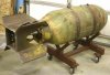
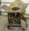
After cutting mine in two, I had a straight shot at the plaster. I used a dig bar for hours on both ends, causing my arms a two week recovery time. I am a very tenacious person who will jump into anything, no matter how hard the work is. I found strength and endurance I did not know I had removing that plaster.

It was 600 pounds of some tough stuff, in which I removed every last drop. I cannot imagine the difficulty you experienced, having to work through a 12 inch hole?

Your piece is very, very nice. I wish it could talk, even more so than mine.

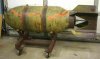
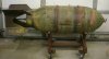
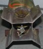
As you can see, my casings "as purchased" paint was similar to yours. Where did you find yours? Do you have a story? Mine just came off of a farm and was pulled out of it’s former resting place, waiting on me to pick it up.

Pulling the thing home on a trailer, my friend and I talked about what we would do if we got pulled over. If asked what we had, my friend replied "It is a boat anchor. They told us the get the heaviest thing we could find!"

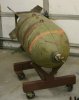
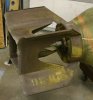
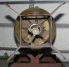
Also, concerning the rings of primer on our casings; my 500 pound AN-M64 came with an original pair of those shipping pads/rings.

00222.jpg
 
Last edited:
Hey Hazord!

For the life of me, please forgive me if I have read your measurements incorrectly, or if the solution is blatantly obvious.

From my point of view, it would seem that you left out some critical measurments. I have tried several times to make a pattern, but where the fin would attach to the cup; nothing is making any sense.

(In blue areas) plase verify that I have read your measurments correctly, and please, please, please provide measurments to areas with the question marks.

Also, I have compared these drawings to your fin. Please relieve me of any doubt by confirming that the angle of the front part of the fin is the same or different when comparing the 500 pound versus the 1000 pound fin. To me they look the same.

DDDDDDDDDDDD.jpg
 
After five hours, here is the sleeve installed of the first of the two fins.

A bit tricky making it, but ultimatley a perfect fit.

AAAAAAAAAAAAAAAB.jpg
 
Other than needing some grinding for cleanup, it is looking great so far.

Here are the extra measurements.
 

Attachments

  • EEEEEEEE.JPG
    EEEEEEEE.JPG
    97.2 KB · Views: 28
Fin number one is complete.

Of all of the measurments that Hazord kindly provided, the only problem I had was attaching the sleeve to the four fins.

As said, I cut the forward part of the fins to exactly 8.5 inches. However, when attaching to the perfect 12" wide sleeve I found the fins were around 3/16" too long. My fin's forward angle, with fins welded on is 8 inches. This may be because my angle is steeper than what is found on Hazord's original fin.

Other than that, if you follow Hazord's measurements, you can produce parts that slide together with no fitting problems.

I put a total of 12 hours into the template for the fins, making a simple die to stamp the reinforcement rims in the sleve, stamping; cutting out the parts and assembling. In this time I produced two sleeves and one set of four fins.

At a local steel distrubutor, I purchased a 10x5 foot sheet of 3/32" thick steel for $138.00, which is almost double what is needed to make 2 sets of fins.

I should have pictures up tonight.

EEEEEEEETT.jpg
 
The dimples look really good on your first assembly! What type of finish did you get on your sheet of steel, pickled and oiled or something else?
 
Here is what I would consider about 80% complete. Some sanding, finishing and final paint and nomenclatrue, and that's it.

888.jpg
 
Last edited:
Top