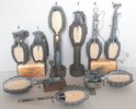
What to do with an US Mk2 handgrenade body? On the added pictures all the possibillities that make a nice picture….
1 - Grenade , hand Mk2.
2 - Grenade , rifle M17, a rifle grenade with concussion fuze
3 - Adapter grenade projection M1, a rifle grenade with a pyrotechnic time fuze
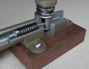
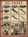
4 - M5 pressure release firing device, a WW2 era pressure release booby trap mechanism
5 - Release firing device M1, a post WW2 era pressure release booby trap mechanism
6 - Pull firing device M1, a ww2 booby trap mechanism
7 - Tension and release mechanism M3, a WW2 booby trap mechanism
8 - M1A1 pressure firing device, a WW2 booby trap mechanism
9 - Chemical delay firing device M1, a WW2 delay booby trap mechanism
1 - The US ‘Grenade, Hand Mk2’ has a cast iron body which is grooved for better grip on the grenade in muddy conditions. The M10A1 fuze uses the so called mouse trap ignition; a spring loaded firing pin is swung round like a mouse trap into the firing cap which ignites the pyrotechnic delay train of 4,5 seconds, after which the detonator is ignited. This will ignite the main charge of flaked TNT in the grenade body.
2 & 3 - The ‘grenade , rifle M17’ and the ‘adapter grenade projection M1’ are described in detail over here:
US rifle grenades M17 and Adapter grenade projection M1 | British Ordnance Collectors Network (bocn.co.uk)
4 - The ‘M5 pressure release device’ is a US WW2 pressure release fuze. It is placed below an object which has to push on the hinged top plate of the fuze with force. If not enough force is applied, the safety pin –which has a groove- cannot be withdrawn as the hinged pressure plate moves up when reaching the groove in the safety pin. Below the hinged pressure plate a mouse trap type firing pin is placed that wants to rotate the firing pin into the firing cap which ignites the detonator.
One can place all kinds of attractive objects on top of the fuze like a pait of binoculars, a rifle or the leg of table, activating the booby trap if the objects are picked up or the table is moved. The disadvantage of the fuze was the rather small pressure plate which must have led to accidents, therefore it was replaced with the ‘release firing device M1’ (#5) after WW2.
5 – The ‘release firing device M1’ , the post WW2 version is described in detail over here:
https://www.bocn.co.uk/threads/firing-device-release-m1-booby-trap-fuze-usa.106466/
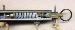
6 - The ‘pull firing device M1’ is a pull fuze. A trip wire is connected to the ring at the end of the fuze and the other side is connedted to a pole or stick. One can use the trip wire just over the ground on ankle height, but it is alo possible to connect the far end of the trip wire to a door handle, activating the fuze when the wire is tensioned if the door handle is rotated.
The aft end of the firing pin has a collar, and a hole is drilled from the aft part of the firing pin to end below the pointed side of the firing pin. Four longitudal slots at 90 degrees each have been machined , also ending below the pointed fwd part of the firing pin. These slots devide the back of the firing pin into four equal segments. These segments are flexible and can be pushed inward , reducing the diameter of the collar. The pull pin with the ring on it has a reduced diameter pin at the front, exactly fitting the hole in the aft of the firing pin, thus forcing the collar to remain it’s large diameter. This collar on the firing pin hooks behind a reduced diameter collar inside the fuze housing. A pressure spring is placed betwee the reduced diameter collar in the fuze housing and the collar on the fwd end of the firing pin , and another sping is placed behind the pull pin. When the wire is tensioned the pull pin is pulled backward –riding it’s spring- untill the reduced diameter pin is pulled from the back of the firing pin, allowing the four segments to move inward, releasing the firing pin to be pulled through the reduced diameter collar inside the fuze housing. The firing pin spring forces the firing pin into the firing cap which ignites the detonator.
7 – The ‘Firing device Pull/release M3’ is described in detail over here:
Mk2 Handgrenade body with a ‘Firing device Pull/release M3’, USA, WW2 | British Ordnance Collectors Network (bocn.co.uk)
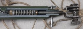
8 – The ‘M1A1 pressure fuze‘ has a spring loaded firing pin. The firing pin has a recess near the back that fits a slot in the pressure piston, which is kept in the upward position by a presure spring below the pressure plate of the piston. The slot has the shape of a keyhole; the lower part (which fits the recess in the firing pin) is rectangular, the upper part is the round which is slightly larger than the full diameter of the firing pin.
On top of the pressure piston three wire protrusions are placed which stick out above the ground when buried. If stepped upon the piston is pushed downward and the rectangular slot moves downward, sliding the round hole over the firing pin, thus releasing the firing pin which hits the firing cap, igniting the detonator, which detonates the main charge of TNT in the hand grenade body.
9 – The ‘chemical delay firing device M1’ is an OSS (Office of Strategic services, WW2 predescessor of the CIA) used time fuze. It is a copy of the British ‘Switch delay No.10’ where the adepter for the Brickfort fuze has been replaced with a threaded adepter with firing cap which enables the fuze to be screwed into a Mk.2 handgrenade body or in a half pound or pound tin of TNT. The combination shown here is meant as a sabotage charge to destroy equipment, either to be placed in an ammo dump. The fuze consists of a spring loaded firing pin, kept in backward position by a thin steel wire, running backwards along a glass vial with Cupric Chloride, packed in a sheet brass pipe. At the back of the pipe a cap is placed with a screw which retains the thin steel wire. To activate the fuze , the vial in the sheet brass tube is broken with a plier, and the Cupric chloride starts eating away the thin steel wire according to this chemical reaction; CuCl2 + Fe → FeCl2 + Cu. When the wire is weakened far enough it will break after which the firing pin hits the firing cap which ignites the detonator, which detonates the main charge of TNT in the hand grenade body.
Regards, DJH
1 - Grenade , hand Mk2.
2 - Grenade , rifle M17, a rifle grenade with concussion fuze
3 - Adapter grenade projection M1, a rifle grenade with a pyrotechnic time fuze
4 - M5 pressure release firing device, a WW2 era pressure release booby trap mechanism
5 - Release firing device M1, a post WW2 era pressure release booby trap mechanism
6 - Pull firing device M1, a ww2 booby trap mechanism
7 - Tension and release mechanism M3, a WW2 booby trap mechanism
8 - M1A1 pressure firing device, a WW2 booby trap mechanism
9 - Chemical delay firing device M1, a WW2 delay booby trap mechanism
1 - The US ‘Grenade, Hand Mk2’ has a cast iron body which is grooved for better grip on the grenade in muddy conditions. The M10A1 fuze uses the so called mouse trap ignition; a spring loaded firing pin is swung round like a mouse trap into the firing cap which ignites the pyrotechnic delay train of 4,5 seconds, after which the detonator is ignited. This will ignite the main charge of flaked TNT in the grenade body.
2 & 3 - The ‘grenade , rifle M17’ and the ‘adapter grenade projection M1’ are described in detail over here:
US rifle grenades M17 and Adapter grenade projection M1 | British Ordnance Collectors Network (bocn.co.uk)
4 - The ‘M5 pressure release device’ is a US WW2 pressure release fuze. It is placed below an object which has to push on the hinged top plate of the fuze with force. If not enough force is applied, the safety pin –which has a groove- cannot be withdrawn as the hinged pressure plate moves up when reaching the groove in the safety pin. Below the hinged pressure plate a mouse trap type firing pin is placed that wants to rotate the firing pin into the firing cap which ignites the detonator.
One can place all kinds of attractive objects on top of the fuze like a pait of binoculars, a rifle or the leg of table, activating the booby trap if the objects are picked up or the table is moved. The disadvantage of the fuze was the rather small pressure plate which must have led to accidents, therefore it was replaced with the ‘release firing device M1’ (#5) after WW2.
5 – The ‘release firing device M1’ , the post WW2 version is described in detail over here:
https://www.bocn.co.uk/threads/firing-device-release-m1-booby-trap-fuze-usa.106466/
6 - The ‘pull firing device M1’ is a pull fuze. A trip wire is connected to the ring at the end of the fuze and the other side is connedted to a pole or stick. One can use the trip wire just over the ground on ankle height, but it is alo possible to connect the far end of the trip wire to a door handle, activating the fuze when the wire is tensioned if the door handle is rotated.
The aft end of the firing pin has a collar, and a hole is drilled from the aft part of the firing pin to end below the pointed side of the firing pin. Four longitudal slots at 90 degrees each have been machined , also ending below the pointed fwd part of the firing pin. These slots devide the back of the firing pin into four equal segments. These segments are flexible and can be pushed inward , reducing the diameter of the collar. The pull pin with the ring on it has a reduced diameter pin at the front, exactly fitting the hole in the aft of the firing pin, thus forcing the collar to remain it’s large diameter. This collar on the firing pin hooks behind a reduced diameter collar inside the fuze housing. A pressure spring is placed betwee the reduced diameter collar in the fuze housing and the collar on the fwd end of the firing pin , and another sping is placed behind the pull pin. When the wire is tensioned the pull pin is pulled backward –riding it’s spring- untill the reduced diameter pin is pulled from the back of the firing pin, allowing the four segments to move inward, releasing the firing pin to be pulled through the reduced diameter collar inside the fuze housing. The firing pin spring forces the firing pin into the firing cap which ignites the detonator.
7 – The ‘Firing device Pull/release M3’ is described in detail over here:
Mk2 Handgrenade body with a ‘Firing device Pull/release M3’, USA, WW2 | British Ordnance Collectors Network (bocn.co.uk)
8 – The ‘M1A1 pressure fuze‘ has a spring loaded firing pin. The firing pin has a recess near the back that fits a slot in the pressure piston, which is kept in the upward position by a presure spring below the pressure plate of the piston. The slot has the shape of a keyhole; the lower part (which fits the recess in the firing pin) is rectangular, the upper part is the round which is slightly larger than the full diameter of the firing pin.
On top of the pressure piston three wire protrusions are placed which stick out above the ground when buried. If stepped upon the piston is pushed downward and the rectangular slot moves downward, sliding the round hole over the firing pin, thus releasing the firing pin which hits the firing cap, igniting the detonator, which detonates the main charge of TNT in the hand grenade body.
9 – The ‘chemical delay firing device M1’ is an OSS (Office of Strategic services, WW2 predescessor of the CIA) used time fuze. It is a copy of the British ‘Switch delay No.10’ where the adepter for the Brickfort fuze has been replaced with a threaded adepter with firing cap which enables the fuze to be screwed into a Mk.2 handgrenade body or in a half pound or pound tin of TNT. The combination shown here is meant as a sabotage charge to destroy equipment, either to be placed in an ammo dump. The fuze consists of a spring loaded firing pin, kept in backward position by a thin steel wire, running backwards along a glass vial with Cupric Chloride, packed in a sheet brass pipe. At the back of the pipe a cap is placed with a screw which retains the thin steel wire. To activate the fuze , the vial in the sheet brass tube is broken with a plier, and the Cupric chloride starts eating away the thin steel wire according to this chemical reaction; CuCl2 + Fe → FeCl2 + Cu. When the wire is weakened far enough it will break after which the firing pin hits the firing cap which ignites the detonator, which detonates the main charge of TNT in the hand grenade body.
Regards, DJH
Attachments
-
 Mk2 grenades and booby traps met nummers.jpg1 MB · Views: 57
 -
 pull firing device M1, #6.jpg761.3 KB · Views: 53
 -
 firing device Pullrelease M3, #7.jpg746.6 KB · Views: 38
 -
 De M1A1 pressure fuze, #8.jpg944.1 KB · Views: 41
 -
 U.S._FUSES_-_USED_TO_SET_OFF_ANTIPERSONNEL_MINES_AND_BOOBY_TRAPS_-_NARA_-_515909.jpg1.2 MB · Views: 54