To the Italians must probably go the prize for designing the most labour intensive and expensive hand grenade ever produced, the SRCM 35. It was made of an abundance of pressed steel and aluminium parts, resulting in a handgrenade with a comparitively light explosive charge and fragmentation sleeve and an allways fuzing system.
The grenade was designed and put into service in 1935. The design was the follow up of the Breda and OTO grenades which were roughly of the same design. These grenades were infamous for their high number of highly sensitive duds, therefore called the red devil by British troops which encountered them in the North African desert campain. The SRCM 35 had a new feature; a special spring loaded masking plate (18) that blocked the firing pin (9) from reaching the firing cap (13) of the detonator in case of a dud.
The genade has been produced from 1935 to .1992!
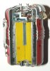
The grenade is build up of an upper (1) and lower (2) outer housing, the top half screwed over the lower half. A small mushroom shaped pin (3) is riveted to the top of the upper half, aroud which the chain (4) of the safety spoon (5) is wound.
On the inside of the grenade, an aluminium bushing (6) is placed around which a lead sleeve (7) is placed, surrounded by rolled up thin wire (8 ), which acts as a fragmentation sleeve. On the inside of this bushing, the firing pin (9) is placed in top. A spring loaded flange (10) is placed over the firing pin in such a way that it will push all objects away from the firing pin point. The explosive charge exists of an aluminium container (11) with a brass cap, housing the detonator well. It is filled with 43 grams of TNT (12). The detonator has a sensitive open firing cap (13). The explosive charge container is placed in the aluminium bushing, resting on the spring loaded flange, the firing cap of the detonator facing the firing pin. The top and base of the outer casing, as well as the top of the aluminium bushing and the base of the explosive charge container have a recess with sloped sides (14) at the centerline. In these recesses a steel ring (15) is placed. The explosives container is fixated in its position in the aluminium bushing by a polished flat strip (16) that is connected to a small brass chain (4). On the other side of the chain the safety spoon (5) is placed which is placed over the top of the grenade. A brass strip with a rubber strap (17) attached to it is placed through the slot for the polished strip from the other side and bent around the spoon. It is the safety pin/strip.
When making the grenade ready for throwing, the brass safety strip is pulled out by the rubber strap, keeping the spoon pressed to the body. Upon throwing the grenade, the spoon falls of, pulling the polished brass strip out by means of the chain. The grenade body will land upon the ground. It does not matter how it lands, as it is designed to be all ways, it will expode in any landing position.
If it lands on the top or base, the explosives container will be pushed into the firing pin, either the aluminium bushing with the fragmentation sleeve will move downward pushing the firing pin into the firing cap-. If the grenade falls onto its side, the inertia will try to move the losse inner parts to the direction of the thrown grenade. This is enabled by the two sloped sides (14) inbetween which the rings are placed. By allowing the explosives container or the aluminium bushing to move sideways up these sloped walls, the explosives container in the aluminium bushing is pushed inward into the firing pin, exploding the grenade.
The masking plate (18) is spring (19) loaded and has to pass to a stepped slot configuration (blue circumferenc). It is placed between the explosive charge container (11) and the spring loaded flange (10).
If the grenade has enough impact energy, the movement of pushing the spring inward will be so fast that the masking plate cannot fall in the lower slot before the firing pin and the firing cap reach one another.
If the grenade has not enough impact enery and the spring will not be moved inward fast enough , the masking plate will be pulled in the lower slot, placing the masking plate between the firing pin and the firing cap, rendering the grenade safe.
Complete length : 85mm
Diameter : 57mm
Weight of the grenade : 240 grams
Weight of the explosive charge : 43 grams of TNT
Regards, DJH
")