British Ordnance Collectors Network
You are using an out of date browser. It may not display this or other websites correctly.
You should upgrade or use an alternative browser.
You should upgrade or use an alternative browser.
No. 5 Filler Thread
- Thread starter adammack
- Start date
I have filler plug for No5 & N0 23 grenades listed as 7/16" x 20 BSW threads. Check this is correct before you make any plugs.Apologies in advance if this has been asked before, but I cannot find an answer. What is the thread size of a No. 5 grenade filler screw?
Many thanks in advance.
I just checked and 7/16" BSW is 14 threads. SO I AM WRONG or it is a custom grenade thread.
Maybe try 7/16" UNF which is 20 threads. I will need to check this tomorrow. Whitworth is 55 and UNF is 60 degrees so it may remove metal but still fit??
Last edited:
king ratgre
Active Member
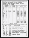
7/16 BSC british standard cycle threadThank you both for your assistance, it's very much appreciated.
That's interesting. A friend of mine who is an engineer said the Mills threads were BSC when he measured them. Is there much of a difference BSW/BSC ? I've got taps and dies for the 7/16 in BSW and they are a match.7/16 BSC british standard cycle thread
7/16" BSW is 14 threads per inch. The No5 filler hole is 20 threads per inch.
Here is the thread sizes for BSC which is 26 tpi so wrong size for filling plugs.
British brass threads are 55 degrees so differ from BSC which is 60 degrees.
Check the common 7/16" UNF as I suggested as taps and dies are common, or cut on a lathe to fit.
Here is the thread sizes for BSC which is 26 tpi so wrong size for filling plugs.
British brass threads are 55 degrees so differ from BSC which is 60 degrees.
Check the common 7/16" UNF as I suggested as taps and dies are common, or cut on a lathe to fit.
Attachments
Last edited:
I have found Mills used UNF on some of his prototypes.7/16" BSW is 14 threads per inch. The No5 filler hole is 20 threads per inch.
Here is the thread sizes for BSC which is 26 tpi so wrong size for filling plugs.
British brass threads are 55 degrees so differ from BSC which is 60 degrees.
Check the common 7/16" UNF as I suggested as taps and dies are common, or cut on a lathe to fit.
king ratgre
Active Member
oops my bad7/16" BSW is 14 threads per inch. The No5 filler hole is 20 threads per inch.
Here is the thread sizes for BSC which is 26 tpi so wrong size for filling plugs.
British brass threads are 55 degrees so differ from BSC which is 60 degrees.
Check the common 7/16" UNF as I suggested as taps and dies are common, or cut on a lathe to fit.
Thread is BSW-form .
It is not UNF. Derived from the American Sellers standard thread, the American Unified National Fine (UNF) was only standardized in 1918 - so somewhat unlikely to have been used in early war British grenade developments.
It is not British Standard Brass, which is only 26 tpi on all diameters.
It is not British Standard Cycle, which has a thread angle of 60°. (Although there is a misconception that BSC is only 26 tpi, other tpi are used for diameters 1/4" to 3/4", for example 20 tpi and 24 tpi.)
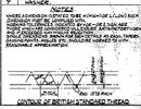
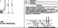
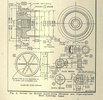
The filler screw thread is 7/16" 20 tpi BSW-form, so thread angle of 55°, and thread profile according to specification. The attached extract from a No.36 grenade drawing illustrates.
It is not UNF. Derived from the American Sellers standard thread, the American Unified National Fine (UNF) was only standardized in 1918 - so somewhat unlikely to have been used in early war British grenade developments.
It is not British Standard Brass, which is only 26 tpi on all diameters.
It is not British Standard Cycle, which has a thread angle of 60°. (Although there is a misconception that BSC is only 26 tpi, other tpi are used for diameters 1/4" to 3/4", for example 20 tpi and 24 tpi.)
The filler screw thread is 7/16" 20 tpi BSW-form, so thread angle of 55°, and thread profile according to specification. The attached extract from a No.36 grenade drawing illustrates.
Attachments
Last edited:
How odd ?!?
I wanted to make a rod attachment for one of my Mills 'No. 22 type' RPG bodies, so I had the thread checked by an experienced engineer who said 1/2" UNF. I was surprised by this as the prototype was made in 1916, possibly 1917 at the latest and I expected BSW. So I went ahead and ordered some 1/2" UNF bolts and they are a perfect fit for the Mills RPG Prototype bodies.
Maybe history is full of inconsistencies?
So what all this tells me is that it is a non standard thread of 7/16" x 20 TPI with a 55 deg. Thread form. Obviously an inhouse custom thread for this use. If you are handy on a lathe & know a bit about steels & hardening, you can make your own tap set.
Non-standard nowadays, but BSW-form was the specified standard at the time extensively used in British explosive munitions. While the thread form was a constant, diameters - whether for components of a No.20 rifle grenade or a No.80 fuze - could appear rather random and were obviously chosen according to the design.
For example, the top body plug diameter of a No.20 rifle grenade was 1.30", and the thread was 20tpi, BSW-form; its base plug was 0.438" (or 7/16") diameter, and its thread 19tpi, BSW-form.
All a bit inconvenient today when ordering a tool at Scewfix or Toolstation, but back in the day many firms had their own toolmakers whose sole task was to make and maintain taps, dies, milling ends and lathe tool bits, &c.
Last edited:
Maybe history is full of inconsistencies?
No, and it's not UNF. I have taken the thread gauge to the Mills RG base plug shown below and it is 1/2" 19tpi, BSW-form.
Attachments
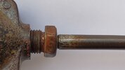
Well there can't be much in it. My friend measured it as UNF and a 1/2" UNF fits perfectly. Perhaps the two standards meet here?No, and it's not UNF. I have taken the thread gauge to the Mills RG base plug shown below and it is 1/2" 19tpi, BSW-form.
Your friend did not measure it correctly. With a difference of one thread per inch it is usually possible to insert the one into the other for several threads. If the socket component is deep enough, ultimately the steel bolt or rod will lock, or if screwed hard enough will chew up the cast iron socket threads - and then lock.
That said I'm not trying to disabuse you of the view that it is UNF if that is what you want to believe.
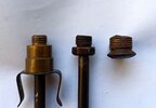
Since 19tpi BSW-form was a preferred thread for base plugs, an image of three examples, left to right, Hale No.3, Mills experimental RG, TW101:
That said I'm not trying to disabuse you of the view that it is UNF if that is what you want to believe.
Since 19tpi BSW-form was a preferred thread for base plugs, an image of three examples, left to right, Hale No.3, Mills experimental RG, TW101:
Attachments
There has been a lot of ill informed and badly researched chat on this subject. So lets have a go and try to do it properly by going to contemporary original source material.A qucik trawl through "google " and "wicki " is NOT the correct way to carry out research and most certainly not to be used to cast aspertions upon opther people.
First off copies of the original drawing of the parts in question ,the complete drawing is reproduced as the end paper in Rick Landers book ,"GRENADE" 2001 Landers Publishing ISBN 1 876713 05 4 a full sizes copy of that drawing was a gift from Seigfried to me many years ago.
The drawing calls for a twent t.p.i. right handed theard of 7/16 inch diameter. [Two pics below]
PROOFABLE FACT NO thread form is called for.So we now KNOW the diameter and the thread count.
At that time there were several agreed threading systems that used a diameter of 7/16 inch and a thread count of 20 t.p.i. Among which were threads for use on copper and brass.LATER these became adopted into the "BRITISH STANDARDS" of which there have been at later dates many updates and reviews.This was done to standardise screw thread systems and forms.Manufacturers have always produced their own threading systems thoughout the whole of human history.However for bulk production using more than one manufacturer an agreed system was fundamental.We know from inspecting surviving examples of the Numbers 5 and 23 and 36 that there were many manufacturers involved.Not all would have been capable of making their own taps and dies.
As for the incorrect statement re. introduction of the unf system lets go once again to source material [Pic. below] Taken from the Fifth edition of MACHINERY"S HANDBOOK published in 1914 by "THE INDUSTRIAL PRESS of New York.For proof of its use before 1918 as quoted in Snufiks message.
For his information there were/are many more sizes and thread counts produced in the range of British Standard CYCLE and British Standard COPPER systems.Now onto measurment of threads diameters and thread counts,the use of a good thread gauge is for INDICATION ONLY,for a diffinitive measment other methods must also be used.
Conclusion The thread is 7/16 dia with 20 tpi of what is NOW called Unified National Fine type.
Last picture is of part of MY tap and die collection. [PIC]
With referance to "Mills man" I WAS THAT ENGINEER


On that we can agree.There has been a lot of ill informed and badly researched chat on this subject.
See below.So lets have a go and try to do it properly by going to contemporary original source material.
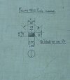
I attach a clear and focused image (1st image) which I took from an original inspection drawing, CIW1968. It clearly shows 20 tpi RH and 0.43" diameter. The thread form, which is a critical set of parameters for mass manufacturing, is not shown on this drawing, because it is the British Whitworth standard, taken as read, and noted in external manufacturing guides. I also attach a part of another (No.36) grenade drawing, which I included in post #10 above (2nd image). This drawing does have specific mention of the thread form, which is the BSW.The drawing calls for a twent t.p.i. right handed theard of 7/16 inch diameter.
PROOFABLE FACT NO thread form is called for.So we now KNOW the diameter and the thread count.
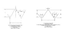
At this point it is worth adding a comparison of BSW and UNF thread forms, because they are literally different in contour, not just in the thread angle. The comparison specification drawing shown (courtesy Britishfasteners website) is self-explanatory (3rd image). Note that, unsurprisingly, the thread height, radius and angle shown on the grenade drawing excerpt match the BSW specification drawing.
In short, British- and Commonwealth-made WWI explosive munitions used the BSW form, and for very good and obvious reasons. (Even Germany had some munitions components that used the BSW-form, as they were made with machinery and tools supplied by the UK pre-war.)
To emphasise the point I include two drawings of British 18-pr components (cartridge and primer) which do explicitly state the thread forms used, viz 14 tpi RH BSW for the primer body and 36 tpi RH BSW for the anvil.
UNF is an American standard thread, which was standardised along with UNC in 1918. UNF was effectively identical to the previous SAE (Standard American Engineers) thread used until 1918, and SAE was in turn based on the American Sellers thread. UNF was not used by the British munitions industry in WWI. It is my understanding that it was only during WWII that the UK started using Unified threads to replace Whitworth when we adopted various US fuzes.As for the incorrect statement re. introduction of the unf system lets go once again to source material [Pic. below] Taken from the Fifth edition of MACHINERY"S HANDBOOK published in 1914 by "THE INDUSTRIAL PRESS of New York.For proof of its use before 1918 as quoted in Snufiks message.
I did make mention of this in post #10 - "Although there is a misconception that BSC is only 26 tpi, other tpi are used for diameters 1/4" to 3/4", for example 20 tpi and 24 tpi."For his information there were/are many more sizes and thread counts produced in the range of British Standard CYCLE .
It should certainly enable a user to measure the threads per inch accurately at the very least, so 19 tpi on a component that has a 19 tpi thread, for example.Now onto measurment of threads diameters and thread counts,the use of a good thread gauge is for INDICATION ONLY,for a diffinitive measment other methods must also be used.
No, it is not UNF. It is British Standard Whitworth.Conclusion The thread is 7/16 dia with 20 tpi of what is NOW called Unified National Fine type.
I WAS THAT ENGINEER
Attachments
Your friend did not measure it correctly. With a difference of one thread per inch it is usually possible to insert the one into the other for several threads. If the socket component is deep enough, ultimately the steel bolt or rod will lock, or if screwed hard enough will chew up the cast iron socket threads - and then lock.
That said I'm not trying to disabuse you of the view that it is UNF if that is what you want to believe.
Thanks for that reply.
Not being an engineer I do find all these different standards confusing, so I tend to rely on people with experience that I don't have or published tables.
Here's some photos that may help or hinder the argument. They are however material fact and exist.

Here's the 1/2" UNF Bolt plus the prototype Mills RPG.

The UNF Bolt inserted into another prototype RPG body

And again in another body.
So I hope these show that the 1/2" UNF Bolt was a perfect fit in the Mills RPG bodies. The bolt screwed in 100% with no jamming, no damage to the threads and no locking. So John Landon's opinion was correct, as proved in reality.
What I do find confusing is that BSW tables show 1/2" BSW as having 14 TPI. Was that just the ideal pairing?
I did of course do some internet searches and one search where I simply put in 1/2" 19TPI BSW came back with "A 1/2" 19TPI thread is not a BSW thread. BSW threads have a coarser thread than other types of thread".
It went on to suggest that 1/2" 19TPI was actually a BSPP - Pipe thread. Interesting. There have also been suggestions that some makers used cycle threads BSC and the fact that some Mills makers were cycle and motor cycle makers opens this as a possibility??? After all the product was disposable and destined for a short life. Also post manufacture inspection didn't include thread sizes as far as I can see from the original documentation.
As I say I'm not an engineer. None of us were around 100 years ago in factories or workshops.
That's part of what makes this area so fascinating! It also shows how forums can be a great place to learn.