What's new
British Ordnance Collectors Network

This is a sample guest message. Register a free account today to become a member! Once signed in, you'll be able to participate on this site by adding your own topics and posts, as well as connect with other members through your own private inbox!

No. 5 Filler Thread

So I hope these show that the 1/2" UNF Bolt was a perfect fit in the Mills RPG bodies. The bolt screwed in 100% with no jamming, no damage to the threads and no locking. So John Landon's opinion was correct, as proved in reality.
The thread depth of the RG socket is about five to six threads, so even being 19 tpi it is no surprise it accepts the 1/2" UNF bolt. If the thread depth was around 10 threads or above, the bolt would start to jam - although that becomes irrelevant if one really wants to believe the 1916 RG thread was somehow cut to an American standard, whether called UNF or SAE.

What I do find confusing is that BSW tables show 1/2" BSW as having 14 TPI. Was that just the ideal pairing?

I did of course do some internet searches and one search where I simply put in 1/2" 19TPI BSW came back with "A 1/2" 19TPI thread is not a BSW thread. BSW threads have a coarser thread than other types of thread".
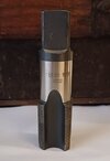
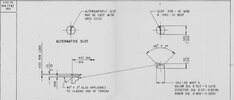
True 1/2" BSW is actually 12 tpi, and is a nut or bolt you could once go into a shop and buy off the shelf. BSW form is any other tpi BSW contour thread that can be turned by lathe onto bar stock - or produced as a cutting tool. Often for custom jobs. In point of fact,1st image below shows a 1.25" 20 tpi tap. Note it is marked W/F - Whitworth Form.

(The BS Fine and BS Pipe standards are also BSW form, and some British WWI grenades used BSP components, for example No.19, No.34 and TW101.)

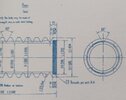
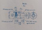
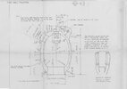
The 2nd and 3rd images show the body plug and base plug of the No.20 rifle grenade, from drawing CIW 3022, taken from the inside cover of Landers' book "Grenade". The body plug threads are 1.3", 20 tpi and the base plug threads are 0.43", 19 tpi - these threads are Whitworth form. It would be interesting to hear how anyone subscribing to the UNF view would reconcile such custom parts.

It went on to suggest that 1/2" 19TPI was actually a BSPP - Pipe thread. Interesting. There have also been suggestions that some makers used cycle threads BSC and the fact that some Mills makers were cycle and motor cycle makers opens this as a possibility??? After all the product was disposable and destined for a short life. Also post manufacture inspection didn't include thread sizes as far as I can see from the original documentation.
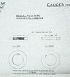
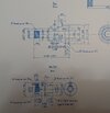
All manufacturers, whatever their background, worked to the same manufacturing and inspection drawings. Inspection was rigorous. Post manufacture inspection did include threads - the 4th image below shows the drawing for manufacture of a base plug gauge.

None of us were around 100 years ago in factories or workshops.
The surviving artifacts and the huge amount of existing primary source documents and photographs describing every detail of munitions manufacture do a good job of informing us.

Finally, the 5th image below shows the detailed drawing for the filler screw of the No.36 grenade. It explicitly states Whitworth Standard...
 

Attachments

  • BSW form Mills base plug tap.jpg
    BSW form Mills base plug tap.jpg
    42.4 KB · Views: 7
  • Body plug, Hale RG.jpg
    Body plug, Hale RG.jpg
    88.3 KB · Views: 8
  • Base plug, Hale RG.jpg
    Base plug, Hale RG.jpg
    113.3 KB · Views: 8
  • Base plug gauge.JPG
    Base plug gauge.JPG
    92.4 KB · Views: 7
  • 36 filler screw.jpg
    36 filler screw.jpg
    88 KB · Views: 7
Last edited:
I admit that my pictures are of poor quality ,however their origins were cited in my reply should anyone wish to view the originals,so lets try and keep this discussion on an adult level.
The drawing ,PART of which you show is of a much later date than the early production of NOS. 5 , 23 and early 36 we are talking about.The fact that a scrap detail of a whitworth thread form is drawn DOES not mean that it was infact used .To read the dawing correctly one needs to read the list of amendments and changes added to the drawing.What you have attatched is NOT a PRODUCTION drawing. In the real world what is produced by a design/drawing office is not an engineering drawing suitable for manufacturing use .During the design stages various iterations would be drawn later AMENDED by production engineers .Taking into account materials,means of production .costing etc etc.This information would be applied to the production drawing.So if you would kindly supply a copy or source for one of Mills original contemporary production drawing this mater would be settled.The nearest we have is cited in my text.
There has never been a "standard" 7/16 x20 screw thread ,thats not to say that a screw thread of 7/16 x20 with a whitform could not be made.That would however be a non standard special. Requiring extra cost and time to produce and issue to manufacturers and due to which not easily avadable to outside contractors in use in bulk productionat that time .Following a lecture givern by Sir Joseph Whitworth regarding standardisation of screw threads to the Institute of Civil Engineers soon after his acceptance into that body [c .1841] answering questions about the suitability of his system to use in various matetrials he admitted to the them being more suited to use in cast iron for wrought iron and less so the more ductil non ferrous materials.[Sir Joseph Whitworth Norman AtkinsonSutton Publishing 1997 ISBN 0-7509-1211-1 pages 130 ff ] and hence what became the accepted use of greater thread counts in softer materials
I have already proved that what we NOW call UNF. was in wide spread use in the time period we are talking about.Use by aero engine and automobile manufacturers amongs many others.PRE 1918
I fail to understand why you needed to go off subject with your pictures of objects that have relavance to this discussion.[Would it be of use if I were to attatch a fuzzy picture of my ACME threaded car jack?]
Your citing of a " fixing supply company" is rather poor and bears little relavance to this disscusion far better would be the correct POST era International Standards [ISO,s for the threads concerned]
Your use of a thread gauge as I have already pointed out is not accepted practice for the CORRECT identification of a screw thead all they are capable of is giving a thread count [t.p.i.] and most certainly gives no indication of the diameter or " class" of thread, vital for understanding how it fits and works.
In your reply you mention the use by the Germans of British supplied machine tools you seem to have a fundamental failure to understand how screw threads are generated,because the machines were British made does not mean they could ONLY make British threaded parts.The fundamental control parts of these machines were master screw threaded "lead" screws ,even the Germans would know to either order the correct thread system or would be capable of making them.
One last question for now why do you keep refering to a 19 tpi thread? 19 is a prime number and a bitch to generate using a stand lead screw [6,8,12,and rare 4 tpi] unless a very complicated cascade of change wheels are set up.It is however used in special situations and on some pipe thread systems and for large sizes.
Millsman has told us and shown that he has in his collection other early development articles that use U.N.F. threaded components
Attatched below just for interest.

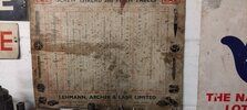
CHART.jpg
 
I understand that you are convinced that British industry in WWI used UNF as the thread standard for production of its explosive munitions. My position is that British industry used Whitworth form (not just off the shelf BSW/BSF tools) for munitions throughout, whether grenades, mortar bombs, aerial bombs or shell, fuze and cartridge case components. From the substantial numbers of primary source documents I have accessed over the past 20 years, I am happy with that, and I have certainly never seen reference to American threads (SAE/UNF) in WWI British-made explosive munitions.

I attach (1st image) one final relevant part of the inspection drawing for the No.36 grenade, IDW (TW) 360, which explicitly states on this printing the use of Whitworth standard form threads for both filler screw and centre piece. Take it or leave it.

There has never been a "standard" 7/16 x20 screw thread ,thats not to say that a screw thread of 7/16 x20 with a whitform could not be made.
One last question for now why do you keep refering to a 19 tpi thread? 19 is a prime number and a bitch to generate using a stand lead screw [6,8,12,and rare 4 tpi] unless a very complicated cascade of change wheels are set up.It is however used in special situations and on some pipe thread systems and for large sizes.
Millsman has told us and shown that he has in his collection other early development articles that use U.N.F. threaded components
Given that according to your UNF-centric argument, 7/16" 20 tpi has to be a UNF, and every thread has to be a UNF standard tool, one last question: how do you reconcile the 7/16" 19 tpi - as shown in the base section and base plug of Inspection drawing CIW3022 for the No.20 rifle grenade (from Landers "Grenade"), 2nd image attached.

I keep referring to the 19 tpi thread as it was the common base plug thread used for rifle grenades, and along with many of the other custom thread-diameter combinations for grenade bodies was done by putting BSW form threads on any diameter bar or casting. The Ordnance Factory Woolwich, and its Inspection Department which oversaw all munitions inspection, was not constrained in its use of threads or being limited to a particular pitch to a particular diameter.
 

Attachments

  • Whitworth.jpg
    Whitworth.jpg
    72.8 KB · Views: 6
  • A 19 tpi base plug.jpg
    A 19 tpi base plug.jpg
    59 KB · Views: 6
Last edited:
The thread depth of the RG socket is about five to six threads, so even being 19 tpi it is no surprise it accepts the 1/2" UNF bolt. If the thread depth was around 10 threads or above, the bolt would start to jam - although that becomes irrelevant if one really wants to believe the 1916 RG thread was somehow cut to an American standard, whether called UNF or SAE.
My only comments on that is that to me is that the 1/2" UNF seems to fit perfectly and if Mills was making an experimental grenade, why would he have to stick to BSW? It could be that manufacturers were asked to review UNF before it was certified in 1918, so why not use it?

If the Germans used BSW for the Kugel and Egg grenades, why can't Mills play around with UNF? After all had the Mills RPG got to production he may have changed to BSW.
 
The thread depth of the RG socket is about five to six threads, so even being 19 tpi it is no surprise it accepts the 1/2" UNF bolt. If the thread depth was around 10 threads or above, the bolt would start to jam - although that becomes irrelevant if one really wants to believe the 1916 RG thread was somehow cut to an American standard, whether called UNF or SAE.
I've just checked the bodies of the two prototypes RPGs shown in the photos and both have twelve threads whereas the part screwed in holding the rod only has 5/6. So the 1" UNF bolt looks well at home.
 
My only comments on that is that to me is that the 1/2" UNF seems to fit perfectly and if Mills was making an experimental grenade, why would he have to stick to BSW? It could be that manufacturers were asked to review UNF before it was certified in 1918, so why not use it?
I've just checked the bodies of the two prototypes RPGs shown in the photos and both have twelve threads whereas the part screwed in holding the rod only has 5/6. So the 1" UNF bolt looks well at home.
UNF did not just appear instantly in 1918. What happened in October 1918 - in very large part because of experience with wartime production - was that the American Engineering Standards Committee (AESC) was founded, made up of the various American Engineering Institutes. The AESC was instrumental in driving further standardisation across US industry, thread standards being just one important area. Before that point in 1918 SAE was one screw standard used in the US, though not likely to have been used by UK munitions manufacturers, who answered to Woolwich Arsenal. Woolwich used Whitworth.

The most likely situation is that Mills in his experimental work was putting BSW thread forms on whatever components needed threading. I have half a dozen of those experimental RG bodies, three tapped. Trying out the single base plug available to me on the threaded ones, it turns out that two different threads have been used on different bodies. If trying a UNF bolt, and the pitches do match as you are finding, then the bolt might take off a very small amount of metal as it goes in.

As for the Mills No.5, 23 and 36 filler screws, they were easily machined to BSW form thread from aluminium or brass bar on a lathe. A modern UNF screw will go into the Whitworth filler screw hole, but shaving or upsetting a small amount of metal in the process. Thereafter the filler hole thread will certainly take both new UNF and original filler screws. I do have a couple of No.5 bodies where I think previous owners might have applied a UNF tap to "clean" the threads.
 
Last edited:
Snufkin your latest missives as per your previous contains yet more waffle and obfuscation .One of the outstanding joys of this site is its content of academic information ,in fact information that is not only learned but has and will save lives
The subject of this thread is the "Number 5 filler thread." Designed by Mills Manufacturing.Not later production of 36 or other ordnance so lets stay with it and not wander off.
At no time have I made the sugestion or statement that what we NOW CALL THE UNIFIED SERIES OF THEADING was adopted for the production of all munitions.Your comments about POST war standards is not relavant to this discussion,I have proved that what we NOW call UNIFIED THREAD SYSTEMS were certainly avaidable from 1914 onwards cited in Machinery"s handbook [you really need to get a copy it is still regarded as the engineers bible,along with the two voluimes of "KEMPS" a British publication.] Despite it being an American system it was available and used world wide during the period we are talking about.
Yet again you have attatched yet more scrap views of drawings which have no relevance to the subject under disscusion.Your comment about Woolwich is only patially correct they would have taken into account the material/materials final intended use etc etc BEFORE MAKING A FINAL CHOICE of threads thats why they were the "design authority" There WERE and still are many differing threading systems avaidable and thats before we get to specials and modified series [e.g. UNF SF UNF EF etc etc] and maunufacturers own.
It is of little interest how many papers you have read if you cannot understand the wider context of the matter they contain .Being able to read and understand what a drawing displays AND what it does not.The basIc knowledge of production methods machine tools and tooling ,metallurgy both currant and historical practices would help you interprating and understanding that information.
I would suggest that as a manufacturer /designer Mills would have used what he knew and what he had.Millsmans examples would seem to support THAT statement.
 
This thread seems to be getting quickly out of hand,keep it on topic and not personal or it will be removed
Admin
 
All manufacturers, whatever their background, worked to the same manufacturing and inspection drawings. Inspection was rigorous. Post manufacture inspection did include threads - the 4th image below shows the drawing for manufacture of a base plug gauge.
I'm not sure that's 100% correct. The Inspection notes themselves are a bit lightweight. Gauging didn't come in from the start, and I'd contest it was fairly pointless if everyone was, as you say, using the same standard sizes.

There were failures of inspection at all levels. A batch of grenades send from Belfast to the Warmley filling factory had 7500 rejected after they had been inspected and stamped by a Woolwich inspector. I've also seen a story where a filling factory manager would take a box of 12 rifle grenades, fire them into waste ground at the back of the factory and if he had 12 bangs signed off the whole weeks production. Hardly scientific.

I spent a lot of my working career as a qualified system auditor. Qualified by HM Treasury for Government work and by the Institute of Internal Auditors for commercial work. We used to interview staff at all levels, check documentation and compare it to the reality of the system, factory production etc.

There are three systems:

1. Prescribed system - What it says on the paperwork, manuals and process documents.
2. Perceived system - What Managers and supervisors think the system is.
3. Actual system - What is really going on in the office, factory, data centre etc.

I can assure you that Prescribed systems account for about 75-80% of what goes on and in many cases it's less than that. In reality people on the 'shop floor' modify procedures, 'forget' pointless procedures and I do not think factories or PEOPLE in the Great war would be any different. In fact work study done in Victorian and Edwardian factories proves this.

So faith in the Prescribed system alone is a bit pointless.
 
I'm not sure that's 100% correct. The Inspection notes themselves are a bit lightweight. Gauging didn't come in from the start, and I'd contest it was fairly pointless if everyone was, as you say, using the same standard sizes.

There were failures of inspection at all levels. A batch of grenades send from Belfast to the Warmley filling factory had 7500 rejected after they had been inspected and stamped by a Woolwich inspector. I've also seen a story where a filling factory manager would take a box of 12 rifle grenades, fire them into waste ground at the back of the factory and if he had 12 bangs signed off the whole weeks production. Hardly scientific.
Some fair comments, and my rather broad statement that inspection was rigorous was made to be deliberately concise (I didn't want to inflict a whole lot of waffle and obfuscation...). Throughout 1915 and into early 1916 inspection was certainly anything but rigorous.

Expansion of inspection staff and the manufacture of gauges across all classes of munitions was a very serious concern as British industry adopted a total war approach after June 1915. It was a huge undertaking to recruit, train and find accommodation for the thousands of new examiners required. Grenades presented just one subset of the problem, and up until the end of 1915 many firms making and filling grenades conducted very limited sampling of output. In early 1916, complaints from the front of failures of Mills grenades and numerous accidents with them, prompted the Ministry to stall production until new examiners could be recruited, trained and deployed - mostly female. It took several months but finally full inspection was implemented. For example, at the end of February, Perivale Explosives reported "Adequate arrangements have now been made for the inspection of the full output of grenades, and women examiners are being employed."

It was the increase in strict inspection that caused rejection rates of Mills grenades to rocket during 1916. The example you mention of a filling station rejecting grenades passed by the manufacturer is one of many. As for your mention of rifle grenades, that was a disaster and the question of full inspection led even Martin Hale, the inventor of the No.3, to refuse any further orders to make them in 1916.

As for gauging of Mills bombs, that was introduced from the outset - drawings for manufacture of the gauges* were created even as those for the bomb were starting to be issued to the very first half dozen contractors. Gauging and use of standard dimensions of components went hand in hand. Unfortunately, in the early days of production and into 1916, inspection wasn't always something - as you intimated - that was done accordingly to the script.


*The earliest date I have on drawings for gauges for the No.5 grenade is 5th June 1915.
 
It is of little interest how many papers you have read if you cannot understand the wider context of the matter they contain .Being able to read and understand what a drawing displays AND what it does not.The basIc knowledge of production methods machine tools and tooling ,metallurgy both currant and historical practices would help you interprating (sic) and understanding that information.
Thank you Mr Landon for your considered advice. As a chartered engineer who did my machine shop training at Rolls Royce way back at the beginning of my engineering career in the 1970s, I think I can manage.

You are adamant that the Mills No.5 filler screw thread at 7/16" 20 tpi is UNF (or SAE if we are talking war years). Of threads used in production British grenades, those dimensions could be a match for UNF, but it is the only thread that could be UNF (barring possibly some grub screws).

The No.36 Mills filler thread at 9/16" 20 tpi doesn't seem to be UNF does it?

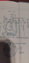
The centre piece thread at 1.25" 20 tpi doesn't seem to be UNF either, does it? (I attach an image to help. Apologies that it is yet another scrap view of a drawing, but it is harvested from a recent post for convenience.)

The No.3, No.20, No.24 base plugs are 7/16" 19tpi - not UNF?

The No.3 and No.20 body plugs are 1.3", 20 tpi - not UNF?

It appears that UNF doesn't really seem to be a popular choice for making trench warfare components. Perhaps a BSW form on any required diameter might have worked, and even on 7/16" it would have kept tooling a little simpler.

As it is germane to the subject of manufacturing of grenades, all Mills types and others, and goes way back to the original poster's question, I have asked you to clarify how just the small selection above are reconciled to your UNF argument. Please humour me by answering the question. I do anticipate now the usual diversion tactic of you launching a personal diatribe against me, rather than answering the question. But please don't this time. Give us all a professional engineering answer to how the other screw threads fit into the UNF argument.
 

Attachments

  • landers.jpg
    landers.jpg
    176.4 KB · Views: 7
Might I start by drawing your attention to two points , the title of this thread " No 5 filler thread "and secondly Spotters post. We now seem to be in a position of "mission creep".
I propose that a new thread are started using where ever possible archival material [where still avaidable ] The body of members can explore and after discussion produce a difinitive record of materials,manufacturing processes etc etc . I would like to suggest that this would be of interest for academic reasons not least the aiding of detecting/proving of modern fakes of what are now becoming increasingly valuble articles.
A personal example of being offered an extreamly rare grenade in very good condition ,its give away ? A slotted part that had characteristic machining marks left by a rotary cutter [slot drill/end mill]. A tooling system not avaidable at that time,assembly completed using a metric thread.
We can start that list with the NUMBER FIVE FILLER SCREW ,Material majority BRASS lesser ALUMINIUM body threaded 7/16 x20 SAE/UNF.
Hi JL
I agree with you in the sense that when ammunition documentation is available, counterfeiters start producing fake historical ammunition in larger quantities than usual - they expect financial success. They are especially attracted to chip machining on multi-axis machine tools... I myself have found several fakes that were never produced in this way - yes, the threads are a sign of this, but not only the centering pits with the impression of the driver and many other clues.
Akon
 
Top