pzgr40
Well-Known Member
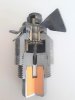
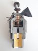
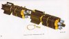
Cutaway model of a WW2 American AN-M 110A1 nose fuze, as used on the 20Lb fragmentation aircraft bom band the 115Lb M70 Chemical bomb.
Functioning of the fuze:
Before bomb release the propeller (01) is blocked by the arming wire stuck trough an extension (02) on the side of the propeller. Upon release the wire is retracted from the extension, allowing the propeller to rotate.
The propeller is connected to a tube (03) which has a gear wheel with 30 teeth fixated to the base (05). The inside of this tube is threaded at the lower part. The assembly rotates over a thrustbearing (04). Inside this assembly another brass tube (06) is placed with a gearwheel with 31 theeth (07) fixated to the base. This inner tube has fine thread on the outside that fits the internal thread on the outer brass tube (03). The firing pin (08) with a pressure spring (09) is placed in the hole in the inner brass tube, held in position in the fuze body by a small radial fixating pin just above the point of the firing pin. Both gearwheels are connected by a small planetary gearwheel (10). The inner tube (06) protrudes above the propeller hub, and a C shaped (or horse shoe shaped) safety segment (11) is placed over it, preventing the firing pin from moving down into the detonator (12). This C shaped segment (11) cannot fall away, as the diameter of the inner tube (06) is larger than the width of the slot in the C shaped segment. The slot is however wide enough to fit over the spring of the firing pin.
As soon as the propeller starts rotating, for each 31 revolutions of the propeller the inner tube (06) rotates once. After 8 revolutions, the inner brass tube (06) has unscrewed and moved down so far that the C-shaped safety segment (11) is allowed to fall away, allowing the firing pin to reach the firing cap upon impact.
Impact will drive the firing pin into the detonator (12), exploding the booster (13) and the main charge.
Regards, DJH
Attachments

Last edited: